Announcement

Collapse
No announcement yet.

Transducer check

Collapse
X
 
  • Filter
  • Time
  • Show
Clear All
new posts

  • Transducer check

    I have been doing some calculations on the transducers I would like to order at Channel Industries.


    Perhaps you could go over it and see that I did not make any mistakes.


    measurements:


    Material: C5804 (Navy type III)


    Length: 1" (25.4 mm)


    width : .5" (12.7 mm)


    thickness: .165" (4.2 mm)


    Voltage generated: .33 Volt/Newton


    Oscillation freq. : 503 kHz


    Array:


    364.7 mm x 4.2 mm


    14 elements = 355.6 mm


    Totale aperature size: 355.6 mm + (13x.7 mm gap) = 364.7 mm


    Horizontal angle : 3/364.7 = .49 degrees (.5 degrees)


    Vertical angle 84 degrees


    Max permissable voltage for this size : 24 kV ( Am not sure about this ..)


    Anyone remarks , suggestions ?


    Regards, Jan

  • #2
    Re: Transducer check and a fishfinder pic


    [img]../images/fishfinder.jpg[/img]


    Jan,


    Sounds good. I like the high res and the width of .5 will help in fixturing. Your math checks out.


    Regards, Tod


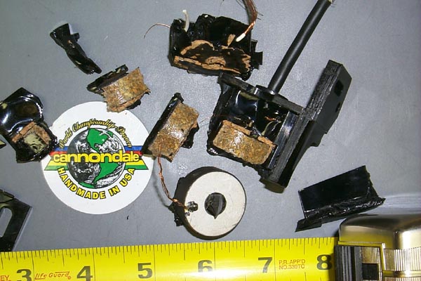
    And here is a pic of the transducer I dismantaled.

    Comment


    • #3
      Re: Transducer check and a fishfinder pic

      Tod,


      I assume the round object is the transducer. It looks like the whole transducer was encapsulated in a cork-epoxy material.


      What kind (manufacturer) of transducer was it?


      How heavy was the bowling ball that was used to open it up?


      Patrick

      Comment


      • #4
        Re: Transducer check and a fishfinder pic

        I don't know manufacturer, but it dim's are 1.1 D x .41 thick and operated at 200KHz.

        Comment


        • #5
          Re: Transducer check

          Hi


          I don't want to be nosy, just to give my opinons:


          >1" (25.4 mm) X .5" (12.7 mm) X .165" (4.2 mm)


          >Array: 364.7 mm x 4.2 mm.


          You plan to mount the crystals with the side against water?


          >Max permissable voltage for this size : 24 kV


          Sounds high to me, Vt-t 5Kv is more reasonable.


          Sture

          Comment


          • #6
            Re: Transducer check

            Sture,


            I might be the only one awake right now other than you and Jan. It is 2am here as I type.


            I think everyone more than welcomes your participation and the knowledge you have brought to the list.


            Any comments you make will likely save everyone a lot of time let alone expense.


            Thanks for the guidance!!!


            Patrick

            Comment


            • #7
              Re: Transducer check

              Sture,


              Welll... ehh .. yes.. is not so good ?


              The element gives its 'movement' to the sides.


              So I was planning to mount them with the sides towards the water.


              I thought 20 kV was a bit overdoing, but that is how I undersood it from Channel Industries webpage what maximum voltage was for this elementsize.


              You suggest a Vt-t (V top-top ?) of about 5 kV


              Does that imply a negative voltage of 2.5 kV and a positive voltage of +2.4 kV ?


              Channel industries warn about to high negative voltages.


              They say it may destroy the element.


              Now we are at it... How does one best drive the transducer ?


              Single pulse like load capacitor with 2-5kV and discharge it over element.


              Or use coil to generate high voltage spike


              or several higvoltage pulses ?


              As you see my knowledge about elements is not that large... but I am learning.. (hehe)


              Regards, Jan

              Comment


              • #8
                Re: Transducer check

                The side-against-water-mount works as good


                as the face-against-water. I have tested both.


                I just didn't know it was common to do it this way.


                The current machine, the "pirate" gives a spike


                of something like 5 KV. Another older machine


                did have a class C transmitter and was oscillating


                +/- 2 KV. I have also tested with square wawe but


                I see no differense to the sine.


                Wich metode that works best I don't know but short


                and intense "pings" is better than longer and


                weaker... of course. The recived echo strenght


                is a function of the ping lenght, but the


                resolution also is.


                Sture

                Comment


                • #9
                  Re: Transducer check

                  Sture,


                  Well, I did it because the elements provided by Channel Industries happen to work like that.


                  Phheeewww, thought there would be a problem with that... )


                  Just for argument sake.


                  What do you think of creating a high voltage spike using an ignition coil system.


                  A coil from an outboard motor is smal and simple.


                  Taken a range of 100 meters the minimum "ping" interval is 133 ms


                  I have to wait at least this time for the echo to return from a target 100 meters away.


                  So I can only ping 1/133ms = 7.5 times a second.


                  Any ignition system can handle that speed.


                  The voltage output is way to high (about 20 kV for any reasonable coil)


                  That is something we might use to make the ping sharp.


                  Of the voltage spike we only use the upgoing side of it.


                  We have 2 voltage comparators or DIAC's


                  One comparator triggers a Thyristor when voltage goes above say 500 volts


                  A second comparator triggers when voltage reaches 5kV and triggers a thyristor that wil short circuit the output, causing the voltage to drop very fast again.


                  When voltage drops below thyristor hold voltage they will reset automaticly.


                  The spike (somewhat a blockpuls now) will have full power from coil behind it.


                  The coil still has quite a lot of magnetic field energy (do not know english word) left.


                  I would thing this would give a short and very strong ping resulting in quite a lot of power in the water.


                  I have not checked the datasheet book if such thyristors are available. (I think so )


                  Specialy the second thyristor needs to burn a lot of energy.


                  We might need to reduce output voltage a bit, this will also let us control the pulse width.


                  Would this be an idea to investigate more ?


                  Regards, Jan


                  P.s. As my fish will have its own power supply I do not think the power consumption will be a problem.


                  I start magnetizing coil only a few miliseconds before actually firing it.


                  Just long enough to saturate coil.


                  This will minimize power consumption.

                  Comment


                  • #10
                    Re: Transducer check

                    Jan,


                    I spent a lot of time scrutinizing the Channel Industries and Piezo Kinetics Websites. (Piezo Kinetics is where Tod is thinking about buying his crystals.. they are at www.piezo-kinetics.com)


                    One question I have is about the max voltage. I got a number different from you and Sture. On page 12 of the Channel Industries catalog it says the max E- for C5804 is 7KV/cm. With a thickness of 4.2 mm, I get 7KV/cm x .1 cm/mm x 4.2 mm = 2.94KV. If I multiply this by 2 to get a peak to peak voltage, I get ~6KV. How did you get 24KV?


                    Also, I noticed that the length of the elements is only twice the width. In the Channel Industries catalog (page it says that the length must be > 3 times width. I'm not sure what the effect is, but I wanted to let you know about it.


                    I noticed that you made the width of the transducer 3 times the thickness.(more or less) I wonder if this value should be exactly 3 times, to aid resonance, or should be offset to prevent ringing.. (same for lenghth to with and length to thickness ratios...)


                    -Bob

                    Comment

                    Working...
                    X