-
The main question at this moment is; how is this procedure done on a Bipolar PI detector? -
Taking into account everything you both wrote, the only conclusion left to me is that I failed to determine the damping resistance correctly.
Or that one (or more) opamps are not good.
This is especially the case when dealing with TL072 opamps. I make a lot of small modules for musicians and I noticed that there are a lot of fake TLxxx opamps on the domestic market.
But let's leave that for later. Let's focus on determining the damping resistor.
How is the damping resistor determined when we have such an H-bridge TX?
Eduardo, I have had a damping "jig" for a long time and have already done it many times on "regular" PI detectors.
However, on this detector I do not see anything irregular in the RX signal when I adjust the damping "jig" in a wider range.
I have a two channel oscilloscope.
On the first channel I connect either TxP or TxN as a reference (trigger) and on the second channel I connect VOP or VON.
Right?
When I did the GS4; I posted this video of the procedure:
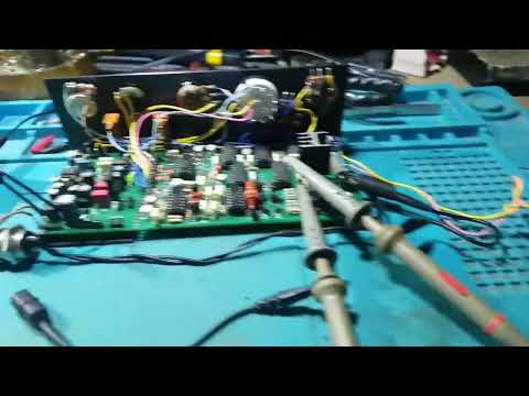
Leave a comment:
-
The way Eduardo's detector works is exactly the same as the way mine works, except that his 4046 audio sounds better. Mine gives a hi-lo response for low conductors and a lo-hi response for high conductors. Iron can end up on either side depending on the nature of the iron, there is no way to make all iron respond in the same way.Originally posted by ivconic View PostLeave a comment:
-
Hi Ivconic. I'm still getting the impression that your detector's damping resistor isn't the right value for the coil you're using. When I first made my detector, I used a 680 Ohm damping resistor, and my detector didn't discriminate under any circumstances. I chose the resistor at random, without even connecting the oscilloscope. To my surprise, the same thing happened to me as to you. The detector didn't discriminate, and it wouldn't detect small targets under any circumstances. Then I connected a multi-turn potentiometer—which you can see in one of my videos is very large and blue—and started turning it until I got the right resistance value. It was 330 Ohms. Sometimes it's better not to have the damping be critical because targets get lost during sampling. If you'd like, I'll take some photos tomorrow of how I have the signal at PIN 7 at the preamplifier output.Leave a comment:
-
The way you wrote this = the way my detector works right now.Originally posted by Carl-NC View Post
There is no need to check anything on the pcb, everything is as you wrote; that's how it works.
But that's not how it should work!
What's the benefit of always having the same behavior on all targets?
Whether it go "wee-waa-wee" at all targets or whether is it "waa-wee-waa" at all targets; it's totally useless in both cases!
Do we understand each other?
What I expected and I think the only correct way for the audio to work is for iron to go "wee-waa-wee" and all other metals "waa-wee-waa" or vice versa, however you like.
Did you watch the video from Eduardo? That's exactly how it should work.
Leave a comment:
-
First, check that both demods are working correctly: IC5a should have a positive-negative target signal and IC5b should have a negative-positive target signal. If these look OK, then check the soldering of you GB pot, especially the pin to the ground channel.Originally posted by ivconic View PostLeave a comment:
-
Hi Algan.Originally posted by algan View Post
Thank you for your effort and dedication. I've tried both versions. The depth increases, but the results are worse. At 100uS, the MOSFETs get very hot, as the coil saturates, and the IRF9640 P-channel MOSFETs have a breakdown voltage of about 200V and can fry. The 80uS version works a little better, but I'm honestly sticking with the original version, as I've managed to improve a few more things on the detector, and I think 50uS is enough for now. My charge pump doesn't drop with frequency because I modified it, and now it's stable regardless of the frequency applied. The changes are shown in the schematic. I replaced the two diodes with two 10K resistors and used Darlington transistors.Leave a comment:
-
Uh then it's a misunderstanding Carl!
That's how it behaves.
But then there is no benefit from such behavior, is there?
Eduardo's video clearly shows that on iron it behaves like "wee-waa-wee" and on "non-ferrous" metals it does the opposite; "waa-wee-waa"... (however I may spell this onomatopoeia of sound behavior).
Regardless of the position of the GEB; you should always hear a different behavior of audio on iron than on non-ferrous metals.
What is the use of the fact that the audio will always behave the same on literally all metals, "this way" when GEB is at minimum and "that way" when GEB is at maximum?Leave a comment:
-
Hi Eduardo, I corrected the code in two versions, you can test if this affects the depth, one version is 80us and the other is 100us. the frequency potentiometer is no problem, the signal does not drop, you can increase the frequency potentiometer all the way.Leave a comment:
-
Hi Ivconic. Please don't be discouraged. This detector works. You've seen my videos, and they're real. I'm sure you've overlooked something on your PCB without realizing it. In the video Carl posted, the detector differentiates the hue between high- and low-conductivity metals. I still don't understand your detector's situation. Look at my last schematic I posted a few days ago; maybe you'll find something useful. I'd love to help, since you're a wonderful person and I've always liked you. Could you show a photo of the oscilloscope, if possible, showing the damping results for your coil? I'd also like to see, if possible, a photo of the jumpers connecting the two RX inputs and the two TX outputs on your PCB?Leave a comment:
-
Once I have solved all the problems on the existing pcb (if I ever do); I plan to draw a different pcb in the near future, with Atmega 328P, 4046 vco audio and I will try to make the pcb as small as possible.
Carl's pcb is "giant" and not convenient to install in smaller boxes.
But again, if we consider the box for the TDI, then Carl's pcb is of ideal dimensions.
This is the least important question.
I am currently interested in the distinction in audio between ferrous and non-ferrous metals and greater sensitivity to coins.
If I fail these two, then I have no plans to do anything further with this detector.
I will leave it in the workshop as an ideal platform for various experiments.
Leave a comment:
-
Provide me exact "pattern" of pulses You need from mcu and I will adjust in the code.Originally posted by eduardo1979 View Post
Also, if You are familiar with the code I posted; you can do it Yourself too, it's easy.
...
As for other questions about the problems I'm having with my detector; I tried a lot of things in the last hour.
First; the audio "buzz" has almost disappeared, it is heard only when the volume is at maximum, and even then it is very quiet, you have to listen hard to hear it.
Bypass cap on pin 7. at LM386 as well as Zobel network at the output solved it to a huge extent!
As for damping... 390 ohms is a good value for a given coil. Again I connected everything to the oscilloscope and checked with the damping "jig".
From approximately 380 ohms to 480 ohms, the damping is "PERFECT", the only thing that comes out of the RX front end "broadens" and "contracts" the RX signal a little bit.
Ok this is the first H-Bridge I'm trying to do the damping on, maybe I don't know how to do it right.
Currently I left 470 ohms on the pcb.
As for connecting the coil, I tried all possible "cross" combinations and still didn't get two audio sounds, especially for ferrous and especially for non ferrous. In all cases, audio behaves the same on all metals.
However, now in one position on the GEB trimmer, somewhere below 50%; I can find a "sweetspot" where the detector does not detect iron AT ALL... but unfortunately not even smaller colored targets, it only detects larger colored targets with a slightly reduced detection range (20-30% less).
I see that Carl has posted multiple versions.
I tried to make the last one.
But I haven't followed in detail (nor been able to find a list of changes in the versions); so it's possible I missed something.
Audio still does not differentiate between iron and non-ferrous metals.
That's the next problem to solve.
Summary:
Damping is PERFECT (if I understood everything correctly),
The coil cable is PERFECT, no doubt about it.Leave a comment:
-
Hello Eduardo
Thanks for the clarification.
But I wanted to see these pulses - on your boards.

Leave a comment:
-
Hi Pechkata. No one showed the pulses because they were shown in the ITMD3 book. Everything is very well explained there. On page 448 is the time base for this detector: PCLK1, NCLK1, PLK2, NCLK2. Then there are the four demodulation pulses: TGTP, GNDP, TGTN, GNDN. I think that says it all. Those pulses match the schematic and PCB layout perfectly.Originally posted by pechkata View PostLeave a comment:
Leave a comment: