

-
The files with components layout will be ready tomorrow, I hope.Leave a comment:
-
Nice, but you still missing the components layout.
Gerbers when opened; only pcb without components layout, pdfs too.
Leave a comment:
-
Voltage drop on green LEDs at current of 5mA is appr. 2V. The voltage on the input of LM337LZ is Vbat-2V. New alkaline 6F22 battery have 9.5V (9.5-2=7.5V input voltage).
"Battery low" module acts at 7.5V battery voltage. Minimal input voltage on the LM337LZ is 7.5-2=5.5V.Leave a comment:
-
Originally posted by Detectorist#1 View Post
Yes, all of that is true. It is missing and I will correct it and add it. I only wanted to draw the essential part for the first time.
Thank you for adding more files. The most important would be with the layout of the components on the pcb file.
I understand about the LED, but I don't understand what voltage you apply to the "In" of the LM337?Leave a comment:
-
Hi ivconic,
We are neighbors - yes I'm Bulgarian. And you are real Serbian - with strong feelings!
First, thank you for good words for this project. Inside have not nothing new as schematic. I just picked up very carefully every component.
Your drawing of schematic is more readable. In my variant, I put many additional information for make more easy the repetition from DIY people.
It is important that the resistors around the coil have to be as 3pcs in series - the peek voltage is appr. 1000V. Variant with one high voltage resistor is inconvenient - too expensive or too big size of the resistors.
In your schematic you dropped module for battery low indication (yes it's optional).
LED diode in the input of LM337LZ is for "Power on" indication only.
Now, I prepare final versions of detailed BILL OF MATERIALS and sketch with PCB layout and component's placings.Leave a comment:
-
TelenoOriginally posted by Teleno View Post
To achieve a delay of 3us to the first sample on a PI can be very challenging. Many factors have to be taken into consideration and many compromises have to be made.
As I am working on this problem at present, I would much appreciate if you would be so kind and help me finding, analyzing the problems, circuits and solutions we could try.
I am starting a new thread for this purpose: THE ELUSIVE 1us TC TARGETLeave a comment:
-
"...recovering of one grain pieces from one inch distance without problem in air and in ground and salt water..."
"...my pinpointer have possibilities to recognize one grain object from one inch without problem..."
"...Remark; very bad results for such a "complicated" schematic? A video demonstration of the work would say a lot..."
I stand corrected!
I wrote this hastily because I'm under the impression of being in a bad mood after accidentally watching something very evil on TV.
Your results are actually very good!
Congratulations!
Proof that I am honest is my effort to draw a schematic clearer and more legible.
As I said, the only thing that is not entirely clear to me is the voltage input to the LM337.
All this motivated me (which is very difficult lately) to dig my pinpointer out of the drawer and test it.
For the first time!
I've had it for over 2 years, I've used it on the sites and I'm very happy with it.
But I've never looked for anything smaller than standard coins.
This video will show more than words. That's why your result with your pinpointer is more worthy of attention.
If we clear up some doubts about the schematic to the end; it will be a very interesting DIY project in these dull winter days.
Finally, I can trace your pcb design and see for myself how what is connected.
But it would be easier if you provided a sketch of the pcb layout with components markings and labels.
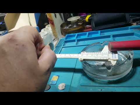
P.S.
Carl;
the proof of my superficiality and laziness is that until half an hour ago I did not know that F-Pusle has a "timeout" function!
Because I hated reading the manual.
I never read any instructions!
So now after 2 years I found out that F-Pulse has a "timeout"!!!

Leave a comment:
-
I don't know what motivates (or prevents) you not to draw a schematic clearly and legibly?
(not only you, I'm addressing all those (and there are a lot of them, especially Bulgarians, btw are you Bulgarian too?) who have the same bad habits, to draw the ugliest and most unclear schematics)
LM337 input is not clear to me btw...
Remark; very bad results for such a "complicated" schematic? A video demonstration of the work would say a lot.
Is it so difficult to draw the schematic a little more clearly, for example like this:
Leave a comment:
-
Now I remember - at my first tests I used ready 22uH-47uH-100uH inductors with ferrite cores and I was surprised that parts with the same induction needs two times different delay for using.
Only different part was the type of ferrite.Leave a comment:

Leave a comment: