Announcement

Collapse
No announcement yet.

Latest Minelab Patent - 11th Feb 2016

Collapse
X
 
  • Filter
  • Time
  • Show
Clear All
new posts

  • Carl-NC
    replied
    Originally posted by Davor View Post
    OK, so you like to calculate with current, I get it. And you calculate current from voltage supplied to the Tx coil. And next magnetic field, and when you go back to the Rx, you calculate flux density to get induced voltage. Duh. Faraday did not complicate that much.

    Even for transformer calculation you need to know current and field only for the sake of core saturation limits. Otherwise it is Faraday through and through.
    Looking at the TX current instead of the voltage better reveals what the heck is going. Just look at the confusion over BBS, and how many people think that just because the drive voltage is a kind of square wave that it must be a type of PI. When looking at the current, it is obviously not. Yet in another design, a similar kind of voltage waveform might produce an obvious PI-style current.

    Another good example is the GPZ, which a lot of people call a VLF. Yet the TX current suggests is it way closer to a PI.

    Leave a comment:


  • Teleno
    replied
    Originally posted by Davor View Post
    OK, so you like to calculate with current, I get it. And you calculate current from voltage supplied to the Tx coil. OK, so you like to calculate with current, I get it. And you calculate current from voltage supplied to the Tx coil. And next magnetic field, and when you go back to the Rx, you calculate flux density to get induced voltage. Duh. Faraday did not complicate that much.
    Once you get a current going in a coil you're stuck with a current problem, for it behaves as a current source. You got to remove that current quickly, not a voltage. Moodz uses a current sink as evidence that the problem can be treated efficiently in the current domain. You can even detect the target's decaying magnetic field as a current in a shorted Rx coil.

    Leave a comment:


  • Davor
    replied
    OK, so you like to calculate with current, I get it. And you calculate current from voltage supplied to the Tx coil. And next magnetic field, and when you go back to the Rx, you calculate flux density to get induced voltage. Duh. Faraday did not complicate that much.

    Even for transformer calculation you need to know current and field only for the sake of core saturation limits. Otherwise it is Faraday through and through.

    Leave a comment:


  • Carl-NC
    replied
    Originally posted by kt315 View Post
    are these pics OK for you? (voltage, NOT current)
    Yes, those are BBS/FBS TX voltage waveforms. Now, what does the TX current look like?

    Originally posted by Davor View Post
    I beg to differ. As the Rx is a voltage sensor, it is voltage that is mostly relevant. You could try a transimpedance preamplifier to get into the current ballpark, but let's not promote confusion.
    Transmitted magnetic field is directly proportional to the TX coil current. Everything else follows from that.

    Leave a comment:


  • Davor
    replied
    Originally posted by Carl-NC View Post
    The voltage is irrelevant other than the mathematical relationship it has to current, due to the fact that an inductor is in play. What matters to the transmitted magnetic field is the coil current. Look at that, and you'll see a different picture.
    I beg to differ. As the Rx is a voltage sensor, it is voltage that is mostly relevant. You could try a transimpedance preamplifier to get into the current ballpark, but let's not promote confusion.

    Regarding targets, it is all the same since coupling is minuscule.

    A diagram you posted earlier that looks as n odd FSK signal with wildly varying amplitude would have a constant voltage amplitude, and for a target that responds the same on both frequencies, it would have equal voltage response. That's why even multifreakers (thanks Dave) have holes, same as PI. That's precisely why BBS works well.

    As for frequency/time, the relevant frequency span would be, say, an octave. The targets have very dull frequency responses. Therefore any kind of processing that collects the most energy from an octave of frequency span may also be regarded as frequency domain. It works for digital filters as well. Heck, even cochlea works that way. Mozart didn't complain.

    Leave a comment:


  • moodz
    replied
    As we can see katuhe supplied to the TX signal is a discrete binary package.
    Note the picture below, the pack begins long pulse followed by 7 short at a frequency of 25 kHz which end again a long pulse, followed by a pause, and again posting.
    Parammetry:
    Swipe SIGNAL- 10 volts (+ -)
    The total duration of the binary packages 470 mksk
    The initial pulse dlitelnostyu- 88 mksk
    Then go straight 7 iipulsov duration of 20 mksk, pause 20 = 25kHz mksk
    Long terminal 88 mksk momentum.
    Pause before sending the next 176 mksk.

    ...it says voltage in the translation.

    Leave a comment:


  • kt315
    replied
    and this
    Click image for larger version

Name:	hp_140.jpg
Views:	1
Size:	66.1 KB
ID:	345070

    Leave a comment:


  • kt315
    replied
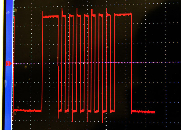
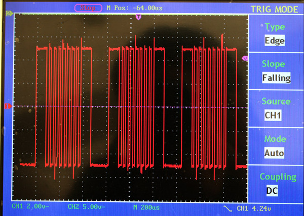
    are these pics OK for you? (voltage, NOT current)

    Как мы видим подводимый к ТХ катухе сигнал представляет собой дискретную бинарную посылку.

    Обратите внимание на картинку ниже, пачка начинается длинным импульсом затем идут 7 коротких с частотой 25 кгц которые заканчиваются опять же длинным импульсом, далее пауза и опять посылка.

    Парамметры:

    Размах сигнала- 10 вольт (+-)
    Общая длительность бинарной посылки 470 мкск

    Начальный импульс длительностью- 88 мкск
    Далее подряд идут 7 иипульсов длительностью по 20 мкск, пауза 20 мкск = 25кгц
    Длинный оконечный импульс 88 мкск.
    Пауза перед следующей посылкой 176 мкск.

    Несколько пачек подряд.


    Одна пачка.


    На данный момент я начинаю перечитывать около 20 патентов

    Leave a comment:


  • Carl-NC
    replied
    What you show is for a traditional PI. BBS/FBS is entirely different.

    Leave a comment:


  • kt315
    replied
    KT, you continue to look at the BBS/FBS
    ---
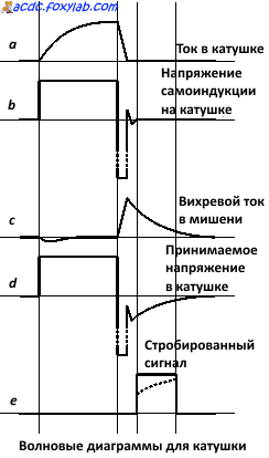
    this pic line 'a' is OK for you? has BBS coil current another form?

    Leave a comment:


  • Carl-NC
    replied
    Originally posted by kt315 View Post
    not same signal Carl.
    General tech discussions on all types of metal detectors: VLF, 2-box, BFO, off-resonance, PLL, etc. Questions, ideas, and anything else that moves you.

    Ok, this is the TX image for a Sovereign Elite and similar MD by Minelab.
    It's composed by a large pulse and a sequence of many small pulse, each
    one have the same time period. I'm not shure but it seem to be a train of
    17 pulse (and this is the number of freq. from 1.5 to 25KHz inside-analizer).

    In this MD the power is from one battery-pack of 12V but the pulse go from
    -10 to +10V (my image have an error...), this is obtained by a bridge over
    the TX coil. On each pulse my Tecktronics show a pure-ring with
    exponentiation decay,
    like a PulseInduction Coil signal without the dumping
    resistor.
    KT, you continue to look at the BBS/FBS TX drive voltage, not the drive current. The voltage is irrelevant other than the mathematical relationship it has to current, due to the fact that an inductor is in play. What matters to the transmitted magnetic field is the coil current. Look at that, and you'll see a different picture.

    The ringing seen by Cossaro in the other thread was not real, it was probably a residual effect of a poorly grounded probe.

    Leave a comment:


  • kt315
    replied
    Originally posted by Carl-NC View Post
    Crane, I think there's pretty much unanimous agreement that things are not always as Minelab describes. 17 frequencies? 28 frequencies? So I wouldn't take their patent wording at face value. I will say that the way the do signal sampling in BBS/FBS appears to be more time-domainish than frequency-domainish, but the reality is it's not as far from traditional FD methods as it appears. And as I said, all detectors -- whether VLF, PI, FD, or TD -- do sampling/demodulation pretty much the same way, all in the time domain. All that differs is the timing.

    In any case, consider the following transmit waveform:

    [ATTACH]35281[/ATTACH]

    What would you call it? Multifrequency? multiperiod? How many frequencies/periods/whatever? Would you process it in the FD or TD? Is it even a practical or realizable approach?
    not same signal Carl.
    General tech discussions on all types of metal detectors: VLF, 2-box, BFO, off-resonance, PLL, etc. Questions, ideas, and anything else that moves you.

    Ok, this is the TX image for a Sovereign Elite and similar MD by Minelab.
    It's composed by a large pulse and a sequence of many small pulse, each
    one have the same time period. I'm not shure but it seem to be a train of
    17 pulse (and this is the number of freq. from 1.5 to 25KHz inside-analizer).

    In this MD the power is from one battery-pack of 12V but the pulse go from
    -10 to +10V (my image have an error...), this is obtained by a bridge over
    the TX coil. On each pulse my Tecktronics show a pure-ring with
    exponentiation decay,
    like a PulseInduction Coil signal without the dumping
    resistor.

    Leave a comment:


  • Teleno
    replied
    Originally posted by moodz View Post
    ...then that is the wording that should have been used in the clear and unambiguous language in a well written patent. :-)
    The language is OK, the skilled person knows what the mathematical representation of a discrete spectrum is and the terminology.

    What's not OK is trying to stop others from using the known state of the art.

    Leave a comment:


  • moodz
    replied
    Originally posted by Teleno View Post
    The definition of discrete SPECTRUM it is "decay parameters (time constants and weights)" (page 8 )
    The signal is "decomposed as a weighted sum of pole responses", that is a discrete SPECTRUM of time constants:


    On page 9:

    "...two time constants were estimated ... for this example .. approximating the two strongest eigencurrent modes in the plate model..."

    Again, the two time constant approximation of a target in ML's "invention"

    ...then that is the wording that should have been used in the clear and unambiguous language in a well written patent. :-)

    Leave a comment:


  • Teleno
    replied
    Originally posted by moodz View Post
    ...hmm the word spectrum does not even appear on p.8
    The definition of discrete SPECTRUM it is "decay parameters (time constants and weights)" (page 8 )
    The signal is "decomposed as a weighted sum of pole responses", that is a discrete SPECTRUM of time constants:


    On page 9:

    "...two time constants were estimated ... for this example .. approximating the two strongest eigencurrent modes in the plate model..."

    Again, the two time constant approximation of a target in ML's "invention"

    Leave a comment:

Working...
X