-
I'm really grateful to all good people as Daren, Don and many others that share their knowledge in this great forum! -
Finally now i've Display and I2C!
Already mounted on a matrix board, with LM7805 to power arduino, LCD and opamps (not yet mounted).
Connected Pushbutton (i've not encoder with pushbutton...used one apart), buzzer, encoder, voltage divider for battery check.
Everything is ok...wow! Great SW you made Daren! Very nice and complex!
I changed multiplier of battery check...now precise as a multimeter! Changed tipical values in % to suit to my lead-gel 12V accu. (and resistor tolerance).
Find a little mistake on your scheme:
3, 4 and 5 indicated as encoder pin A, B, Button are not correct.
Accordingly to your SW they are pin 2, 3, 4:
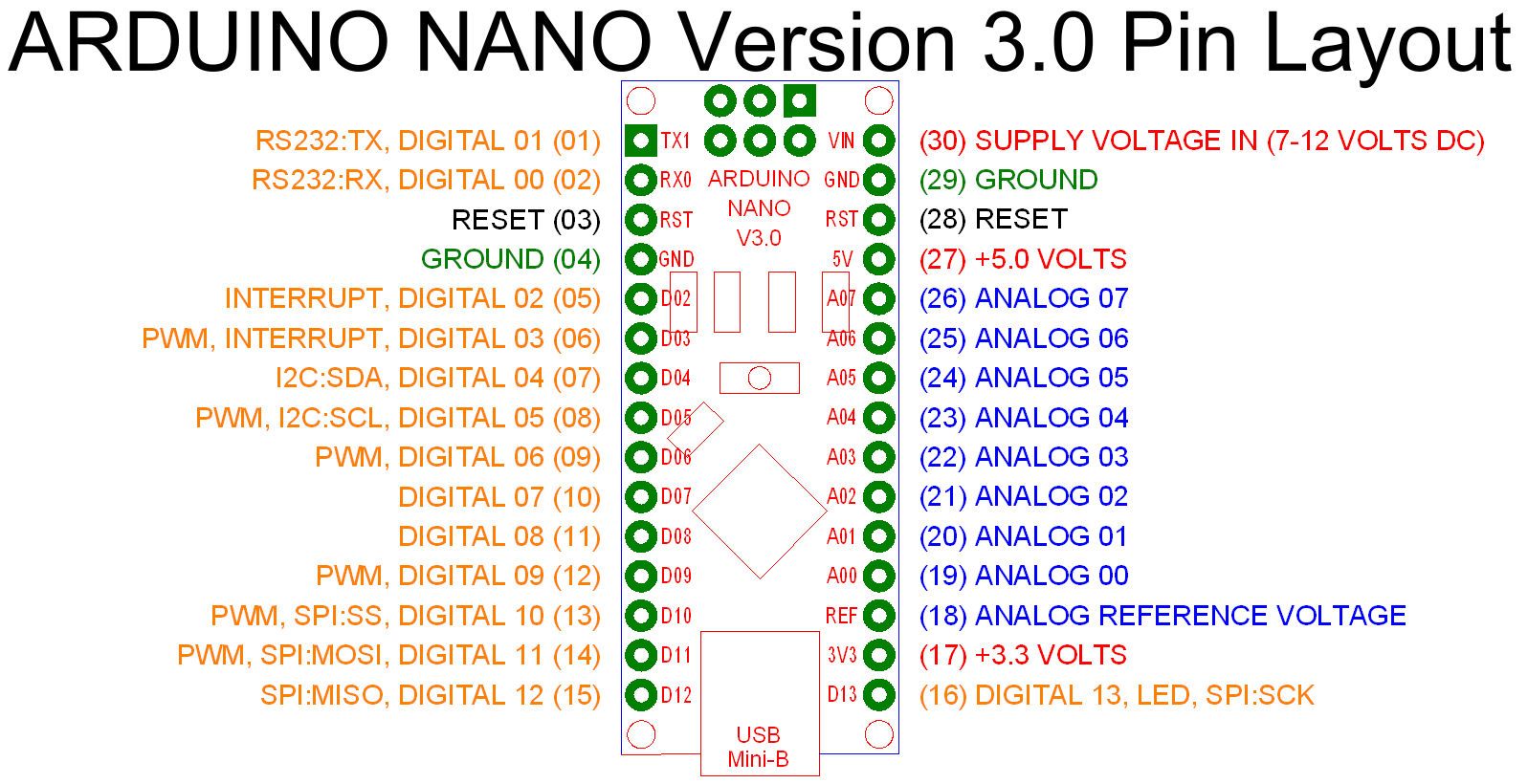
Another error was in a damn image i used to understand which pin to use on arduino NANO for SDA and SCL...Code:#define PIN_ENC1 2 //Arduino 2 -> encoder pin A #define PIN_ENC2 3 //Arduino 3 -> encoder pin B #define PIN_EBTN 4 //Arduino 4 -> encoder button pin 0
THIS PICTURE IS WRONG:
SDA is NOT D04 and SCL is NOT D05!
Wasted time to figure out the problem...
THIS PIC IS CORRECT:

SDA pin A4
SCL pin A5
Soon I build operational circuit...if it works i'll enclose everything in a nice box...
Please Daren tell me if you made some changes in HW and SW because i really want to come out the best possible from this VDI...
I have high expectations...hehe!
Leave a comment:
-
Hi Daren,
Are you satisfied with your new modification and progress with Vdi?
I'm curious of the use of it in real soil too. Maybe Don could share his experience with the Vdi he made, finished and mounted on the MD. I hope it is a very useful addiction that work good and stable giving nice indications.
Probably tomorrow i'll get my display + i2c board...so i should have eveything to start the build of my arduino vdi.
I hope to not ask too much Daren, could your share your latest software version so we can made directly the project with your new mods? I'gonna make it directly on a matrix board...
Thanks!
Leave a comment:
-
Daren:
So you now are using an inverting buffer without amplification?On another note: I received MCP602 and replaced LM358; To get the circuit to work correctly I had to remove 0.22u caps and change 1M to 47k.
But if you connect VDI opamps "before" U104 and U105, you could use your original preamp scheme:
...since it should give a gain like U104 and U105 do... I'm wrong?
And since those are all inverting opamps, picking signal after one gain block should be different of picking it after two...
Let me explain better:
Considering disc channel:
U103B pin 1 signal rising : _/
U104 pin 6 signal falling : \_
Your VDI preamp output, signal rising: _/ (to be readed from arduino)
Else if I put VDI preamp after U103B pin 1
U103B pin 1 signal rising : _/
VDI preamp output, signal falling : \_ (to be readed from arduino)
...My toughts are only on the convenience to work with a more clean signal, picking it before a gain block (U104 and U105), to have less noise.
What do you think?Leave a comment:
-
yeah that's what I used. my I2C address was 0x27 I think this one is 0x20 so the device address in the code will have to be updated.
On another note: I received MCP602 and replaced LM358; To get the circuit to work correctly I had to remove 0.22u caps and change 1M to 47k. After looking at the signal I also realized that it is not symmetrical to the offset voltage does not have to be 2.5V. It can be 1V, so there is 4V upper range. For the opamp "+ input" ref voltage divider I put a 10k + 10K trimmer and adjusted to 1V.
Software was also updated to allow for ADC calibration of the MAX input. This allows detection of the saturated opamp and flagging it on the VDI as invalid reading. To calibrate you will have generate a big signal while calibrating. I'll post the code later on...
With 602 and the lower amplification the noise is lower too..Leave a comment:
-
Yes bernte this should be ideal for this project...i'm waiting for a similar display...like daren's one.
I find two of these for opamp: TS921.
this is single opamp so i have to use two of them.
I think that has very nice specifics...for example low noise and rail to rail output. What do you think?
LM358 is not so good as specifics...probably better TL072. Your opinions?Leave a comment:
-

is this lcd dicplay ok for use with the vdi project
without changing tons of code
i takes only 2 wire for signal transfer from arduino to lcd
easier to solder or used with a simple pin connectorLeave a comment:
-
all you have described should be fine. I'm waiting for 602 opamp to put in, it has 0-5V swing on the output. 358 has output I think 1V less than Vcc, so yeah if you bump Vcc to 6 you will get nice output range. (I think you meant 7806, or just use diods to loose some voltage).
As far as the input point for circuitry U104 and U105 outputs were used because I they have good levels (did not look saturated). I intended to make opamp with gain 1 just to buffer signal up. After playing with the circuit 47K/1M gave the output that was OK. Its the 0.022u that affect the gain a lot. I initially by mistake put 0.22u and was scratching my head for a while because I could not get enough gain. In short: you can get your signal from any point as far as the inputs A0, A1 are 2.5V with no target and then swing up/down preferably without saturation.Leave a comment:
-
To be more clear:
I use this mod from Davor on my TGSL:
It showed a nice improvement in my MD.
But as you see, feedback in U104 and U105 is limited by 2 diodes (not 1 like original scheme)...this makes things not as linear as before. Connecting VDI here and amplificating with another hi-gain preamp should probably degrade the quality of signal to analize in arduino.
Did you tested connecting VDI preamp in U103 pin 1 and 7? You could have less sensitivity but perhaps more precise input for VDI...I'm wrong?
To have a output swing of 0 to 5V in LM358 (and not 0 to 3.7V or 4V) it should be powered by something like 5V + about 1 or 1.3V.
It could be easily made with 78L05 adjusting output:

(image show 1 Ampere LM7805. We could use 0.1A version: 78L05)
6V for example using R1 = 470 Ohm and R2 = 100 Ohm.
Using 12V from battery as Input Voltage for 78L05. It should provide 100mA current.
In this manner you can obtain LM358 with 0 to 5V output swing...Leave a comment:
-
U104 and U105 PIN 6 are not too amplificated and almost binary to drive another very amplificated stadium of Vdi preamp? Should not be better using previous X and R point of TGSL?
For increase output swing of LM358 it could be connected to a more higher positive rail...not 5 of arduino 5V out but maybe a voltage divider + zener from 12V we have...what do you think?Leave a comment:
-
I did some experiments with the sound too, there was not enough fluidity.. Yes you can beep while you display the phase and base your pitch on the phase number. But its not good enough. Original audio conveys more info; signal strength, breaking signal, immediate feedback, etc. Using digital audio all this is lost. You can do very nice digital audio, but at this moment I don't how. Low CPU clock and processing power restricts using more fancy stuff.
You need to express a lot of nuances in the sound to be useful and analog audio does it naturally.
The schematic is basically IDX - VDI front-end with Arduino in the back. Don't mix VCC and RAW on Arduino
Leave a comment:



Leave a comment: