ProScan Pulse Induction Metal DetectorSchematic (PDF-131K)PC Board (JPEG-167K) Parts Placement (JPEG-134K) |
||||||||||||||||||||||||||||||||||||||||||||||||||||||||||||||||||||||||||||||||||||||||||||||||||||||||||||||||||||||||||||||||||
|
Here it is! This is the PI metal detector first introduced in ProScan site (www.polbox.com/p/proscan/schemat.htm). The schematic was redrawn and revised by me (Paulo Viegas) and Piotr from Proscan.
|
||||||||||||||||||||||||||||||||||||||||||||||||||||||||||||||||||||||||||||||||||||||||||||||||||||||||||||||||||||||||||||||||||
|
The components Capacitors: Non-polarized: Use good quality polyester capacitors, except for pF capacitors which can be ceramic. Polarized: Electrolytic, voltage as indicated on plan. Resistors Use 1/4 watt, 1% or 5% tolerance IC's DO NOT USE IC SUPPORTS (sockets), those can create inductance and capacitance, and we do not want that! For 709 I recommend using the TO99 version. VR's Use the mini version, horizontal placement. USE ONLY NEW COMPONENTS
Component List
|
||||||||||||||||||||||||||||||||||||||||||||||||||||||||||||||||||||||||||||||||||||||||||||||||||||||||||||||||||||||||||||||||||
|
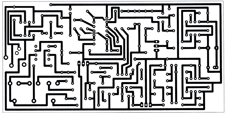
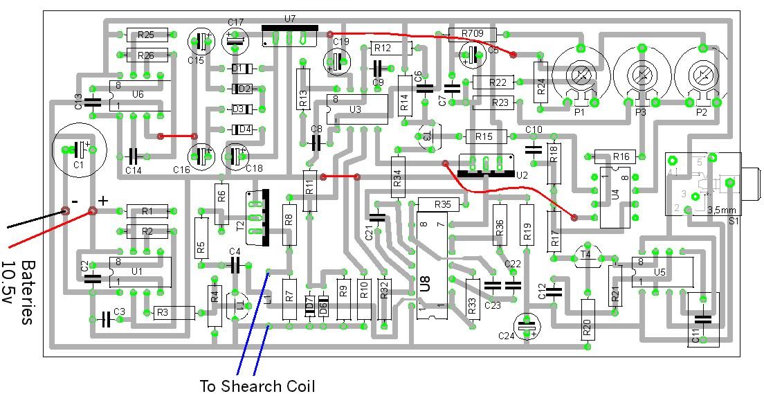
PCB The PCB for this project is a JPG file (PCB1), the final printed dimensions should be ~65mm X ~130mm. I recommend using the photo process to create the tracks, since the circuit is more or less complicated. After printing PCB1 flip the paper, the printed surface is the one that will be in contact with the copper layer. The components placement is in file PCB2. Please note that there's four jumps, make then with standard isolated copper wire. The S1 (jack support) is optional, and can be placed in the case. Keep the components with short leads, and close to the pcb, to avoid capacitance and inductance. Note: I've taken much care in making this pcb, I believe no tracks were forgotten (since this is insured by the software), nevertheless if any error as to be found, please inform me right away. [[email protected]] IMPORTANT After making the pcb, please check the tracks that go inside 4093 pins, insure that they are not short-circuited (correct with a x-acto blade if needed). Circuit Description "Basically U1 is a timer integrated circuit that is wired as a pulse generator. The output on pin 3 is a negative going pulse of a width that determines the width of the transmitter pulse. This is repeated at a certain frequency that is the transmitter pulse rate. This pulse train drives T1, which inverts it so that it is then a positive pulse driving the base of T2. T2 is the transmitter output stage driving the search coil, L1, in its collector. U2 is a voltage regulator that takes the negative battery voltage and gives -5V output for the receiver amplifiers U3 and U4. R7 across the coil is a damping resistor to stop the coil ringing. The live side of the coil then goes through a 300? ohm resistor to pin 2 of U3 which is a wide band receiver amplifier. The two back to back diodes prevent the transmitter switching transients from damaging U3. After amplification the signal goes to the sampling gate T3. This acts as a switch that is closed until a short time after the transmitter pulse has ended (pulse delay) This delay is generated by the 4093 dual monostable which is triggered via C4 from the transmitter waveform. The first half on the 4093 generates the delay duration while the second half generates the time that the gate stays open. U4 is a single ended integrator which takes a running average of the samples of the amplified receiver waveform. When there is no metal near the coil the sample will be approximately zero; bring metal near to the coil and the sampled decaying waveform from the metal will cause the output of U4 to rise. This dc output goes via R17 to the transistor T4 which controls another timer IC, U5, to generate the audio pulses. The audio output is a tick that increases in frequency as metal is brought closer to the coil. The threshold tick is set by P3 that alters the bias on the other input of U4. Headphones can be connected to pins 3 and 2 of the connector on the right of the schematic. A resistor in series here might be necessary to adjust the volume. At the top left of the schematic U6, is another timer that generates a separate pulse train that is then rectified by the diodes D1-D4 to give a positive dc voltage which is then supplied to the positive 10V regulator U7 which gives the positive supply necessary for the receiver IC's. P1 is a preset resistor that sets the dc output level on pin 6 of U3 to 0 volts. It is useful to connect an oscilloscope to this point for testing to see that everything is working OK. The only thing that I can't show here are the various waveforms and their relationship with each other. These are controlled by the components around the timers and the monostables and are fixed by the values given in the schematic. So if everything is assembled right the only setup adjustment is P1." Eric Foster Eric's suggestion: "I would suggest making R8 1K0, R11 1M0 and deleting R9. This will give a gain of 1000 for the first stage and the 709 will be stable with the compensation values given. What sometimes fails rather than the diode is the input resistor R8 and possibly the damping resistor. Both of these resistors experience the peak voltage across them and can go open circuit unless a high quality metal film resistor of adequate rating is used." Acknowledgements
I would like to thank: |
||||||||||||||||||||||||||||||||||||||||||||||||||||||||||||||||||||||||||||||||||||||||||||||||||||||||||||||||||||||||||||||||||