-
I dug out this old pdf. 4046 can be used in many ways.
Good stuff.
Leave a comment:
-
Hi Carl.Originally posted by Carl-NC View Post
I'm stuck and need your help.
I'm drawing the PCB for the Bipolar PI in SMD and I have a question regarding the 74HCT4316 as I see that it gives problems. Could I put a 74HCT4066 instead, making the corresponding modifications on the PCB on the power pins, since they are different? I've also thought about using a CD4066 and adding 4 voltage converters with 4 PNP transistors and 8 resistors just like in the Arduino Nano PI. In your opinion, which of the two variants would be the best?
I'm also going to use a CD4046 for the audio VCO.
Thanks in advance.Leave a comment:
-
Sorry again, I didn't pay attention to the scope of the oscilloscope probe...
Thanks for the video and your time...
I'm glad there are people like you - stay alive and well...Leave a comment:
-
Apologies to Carl and all forum participants...
The video did not show how many volts the peak of the final transistors is...
Something like that...Leave a comment:
-
Excellent job Carl!
That is what I would call a very well made video.
This is what I have asked/rebuked many forum members many times when they present their ideas.
Emersonpaz too, good video.

Leave a comment:
-
Excellent video Carl congratulations, it was very well explained, I believe that if the VCO with the 4046 two tones was integrated into the bipolar project it would be a great improvement, I made an adaptation to the Polish pi
Leave a comment:
-
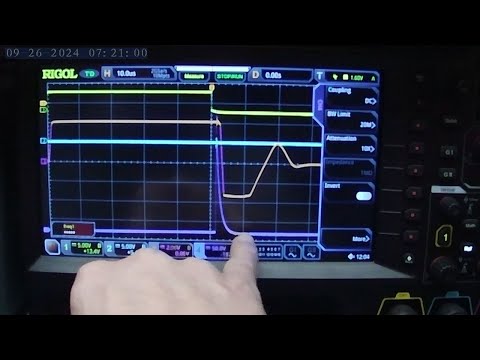
I've created a video describing the Bipolar PI circuit. Sorry for the poor quality, I need some better equipment.
Leave a comment:
-
hello
Has anyone finished this project?
Where is the hex file?
thank youLeave a comment:
-
Yes, I managed to draw two boards 80mmx90mm, but I still have the generator and around the generator, which will also be on a separate board, yes it will be smaller and yes the errors may not be seen until the detector is launched, but it is important, as they say, the idea and everyone can experiment with different variants, the important thing is to try.Leave a comment:
-
In half an hour or so, you can clean up the board that you converted from the Gerber files by marking the unnecessary paths and using the "delete" function. Then you use the "test" function and check for missing connections.If there are any, you restore them using the "track" function. It's laborious, I know, but unfortunately the Gerber import function of Sprint Layout is imperfect.Originally posted by algan View Post
See partially cleaned circuit board.Leave a comment:


Leave a comment: