Announcement

Collapse
No announcement yet.

Bipolar PI design

Collapse
X
 
  • Filter
  • Time
  • Show
Clear All
new posts

  • pito
    replied
    Originally posted by pechkata View Post

    Hi Pito
    Without the chip, nothing is visible.
    Click image for larger version Name:	Екранна снимка (22).png Views:	0 Size:	261.7 KB ID:	444357
    I was testing this part

    Click image for larger version

Name:	image.png
Views:	543
Size:	30.1 KB
ID:	444367​

    Leave a comment:


  • pechkata
    replied


    Leave a comment:


  • pechkata
    replied
    Originally posted by pito View Post
    I made Tx tests, amplitude 1/2 compared to 1 MOSFET circuit, frequency 2x higher.
    So sensitivity will drop.​
    Hi Pito
    Without the chip, nothing is visible.
    Click image for larger version  Name:	Екранна снимка (22).png Views:	0 Size:	261.7 KB ID:	444357

    Leave a comment:


  • pito
    replied
    I only assembled Tx part of the circuit on breadboard

    Leave a comment:


  • Badim49
    replied
    Originally posted by pito View Post
    I made Tx tests, amplitude 1/2 compared to 1 MOSFET circuit, frequency 2x higher.
    So sensitivity will drop.​
    Can you tell me how to assemble a working device and what the latest changes are?

    Leave a comment:


  • pito
    replied
    I made Tx tests, amplitude 1/2 compared to 1 MOSFET circuit, frequency 2x higher.
    So sensitivity will drop.​

    Leave a comment:


  • pechkata
    replied
    Originally posted by Detectorist#1 View Post
    Hi Carl, many of us, ITMD3 readers, are very grateful for your efforts in favor of DIY detectorists to be involved in this exciting hobby!
    Why don't you continue this project until the end?
    But you're starting other projects.
    You are using the fox theory of sour grapes.
    And these photos are not from this project - but it could be continued.
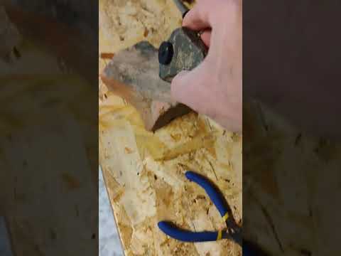
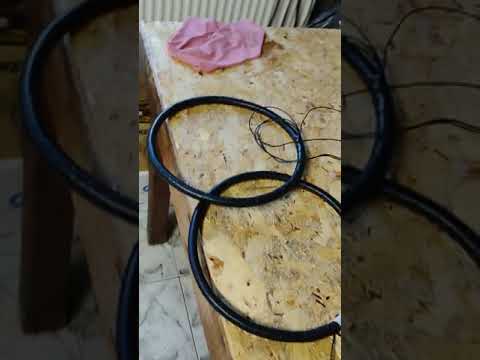
    Click image for larger version  Name:	viber_изображение_2026-01-05_10-17-05-848.jpg Views:	0 Size:	373.4 KB ID:	444342
    Click image for larger version  Name:	viber_изображение_2026-01-05_10-17-05-904.jpg Views:	0 Size:	358.2 KB ID:	444343

    Leave a comment:


  • Badim49
    replied
    Originally posted by ivconic View Post
    And this schematic above is just a "picture" too, for all those who are interested, here is the schematic file.
    The software that is needed is "ExpressPCB",
    (don't get confused, it's a free installation package that during installation also installs a schematic part called "ExpressSCH" in which I mostly draw schematics)
    and you can download it free from here: https://www.expresspcb.com/

    ​And here is the sch file:
    There is a firmware ?

    Leave a comment:


  • h9361
    replied
    Originally posted by Carl-NC View Post
    These are the SAT circuits. Exact same thing as in Hammerhead.
    Thank you dear Carl for your information.

    Leave a comment:


  • Carl-NC
    replied
    These are the SAT circuits. Exact same thing as in Hammerhead.

    Leave a comment:


  • h9361
    replied
    Originally posted by eduardo1979 View Post
    Capacitors are used to filter noise. I don't see resistors R74 and R75 in the schematic.
    See attached (red circle).
    Attached Files

    Leave a comment:


  • eduardo1979
    replied
    Capacitors are used to filter noise. I don't see resistors R74 and R75 in the schematic.

    Leave a comment:


  • h9361
    replied
    Originally posted by eduardo1979 View Post
    There are many versions of the schematics posted on the forum. Please attach the schematic you're referring to so we can identify the specific components you mean.
    Your schematic, attached.
    Can you tell me why you use R74,C43 and R75,C44?
    Is it for reaching a soft audio?​
    Attached Files

    Leave a comment:


  • eduardo1979
    replied
    There are many versions of the schematics posted on the forum. Please attach the schematic you're referring to so we can identify the specific components you mean.

    Leave a comment:


  • h9361
    replied
    Originally posted by eduardo1979 View Post
    Hello.
    Yes, GND and -5V.
    Thank you.
    I have another question, please forgive me.
    Can you tell me why you use R74,C43 and R75,C44?
    Is it for reaching a soft audio?

    Leave a comment:

Working...
X