Announcement

Collapse
No announcement yet.

Baracuda + Micro

Collapse
X
 
  • Filter
  • Time
  • Show
Clear All
new posts

  • moodz
    replied
    Originally posted by Chet View Post
    Hi Mike
    Nice looking board. For the LCD do you plan to use a parallel interface; I didn’t see a serial input listed with that display.
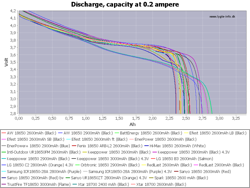
    The 4 x 18650, 16v battery pack should work fine; they fall off quickly toward the end. Setting the low battery alert around 12.6v should be close enough. See some 18650 discharge curves at the website below.
    Have another good day,
    Chet


    http://lygte-info.dk/review/batterie...dium%20UK.html
    ....teleno might be referring to an isr that calls a very tight machine code polling loop that has precise non rentrant timing. Despite manufacturers specifications isr latencies are not guaranteed or fixed. Hardware comparators and counters work best IMHO.

    500 ns timing is practically useless for high spec pi work. 20 ns or better is required.

    Leave a comment:


  • 6666
    replied
    Originally posted by Chet View Post
    I have found the 18650 battery holders that have flat broad metal contacts at each end to really work well. The older types with spiral springs on one end are terrible for loose connections.
    Have a good day,
    Chet


    http://www.ebay.com/itm/Hot-Sale-1-2...ibZWqn2betihMQ
    Thanks have not seen that type before, the spring type are not the best design.

    Leave a comment:


  • Chet
    replied
    I have found the 18650 battery holders that have flat broad metal contacts at each end to really work well. The older types with spiral springs on one end are terrible for loose connections.
    Have a good day,
    Chet


    Leave a comment:


  • Michaelo
    replied
    Originally posted by Chet View Post
    Hi Mike
    Nice looking board. For the LCD do you plan to use a parallel interface; I didn’t see a serial input listed with that display.
    The 4 x 18650, 16v battery pack should work fine; they fall off quickly toward the end. Setting the low battery alert around 12.6v should be close enough. See some 18650 discharge curves at the website below.
    You can buy a serial interface board that piggybacks on the LCD for small money but we don't currently need to reduce the pin count on the Micro so no need for it yet...

    I'd set the battery warning at about 3.3 x 4 = 13.2 and cut off at 3.1 x 4 = 12.4 but the Bara doesn't draw that much current (on average that is), so should be good for most of the day but I would always bring a second set of batteries just in case...

    I've made the board bigger so it will fit nicely inside an aluminium box (100x97x35mm on ebay for about $5/$6), it looks very good with the baracuda Rev 2 inside and just a couple of potentiometers, Earphone jack and coil socket....
    Batteries are a bit tight but I may put them in a separate box... not sure yet...

    @6666, one of the few occasions when buying cheep is playing with "Fire"

    Family give me their broken laptops and have for many years... Only recently did I realise the batteries are still good and the cells will last for a few more years...
    I now have over twenty perfect 18650's and haven't recycled all the laptops yet... I've been able to re-energised batteries with as little as 0.3 volts but most (even after a number of years) were over 1 volt...

    Mike

    Leave a comment:


  • 6666
    replied
    Originally posted by Chet View Post
    Hi Mike
    Nice looking board. For the LCD do you plan to use a parallel interface; I didn’t see a serial input listed with that display.
    The 4 x 18650, 16v battery pack should work fine; they fall off quickly toward the end. Setting the low battery alert around 12.6v should be close enough. See some 18650 discharge curves at the website below.
    Have another good day,
    Chet


    http://lygte-info.dk/review/batterie...dium%20UK.html

    Hi Chet, thanks for that link, its worth the read for anybody interested in using 18650 cells, and basicly avoid any brand that has the word "Fire " in it.

    Leave a comment:


  • scrungy_doolittle
    replied
    Originally posted by Teleno View Post
    My point was time critical matters are better handled by polling interrupt flags rather than ISR, and I proved that with actual code vs. ISR code, and that got you all wired up.

    Still waiting for you to put your code where your mouth is.
    Teleno, you are wrong.
    I'm an embedded software engineer with 25+ years experience in the field. Interrupts are your friend, as well as your enemy. The key thing, is to utilize the resources in the chip sufficiently. And polling is not the way to do that. If you can take advantage of a timer with comparator block, that is the way to do it. and if you can arrange this without interrupts, that is even better. Polling interrupt flags is non-sense, because it defeats the purpose of interrupts. My current product is a medical device. There are 5 interrupts firing very very rapidly. But it is still responsive as heck, and I have 500 ns resolution on my timings.
    It is all in how you program the part. I've probably forgotten more about code than a lot of guys know, just sayin.

    Leave a comment:


  • Chet
    replied
    Originally posted by Michaelo View Post
    The LCD I ordered is: This one http://www.ebay.ie/itm/252311968705?...%3AMEBIDX%3AIT
    As to the backlight, no adjustments, either on or off (the display has an on board resistor)...

    Here's a 3D view of the current board... It's 90x70mm... It's just a starting place... might make it a little neater...
    [ATTACH]36062[/ATTACH]


    For testing I'm using 4x 18650 Lithium Ion Batteries and one 5 volt reg for the micro...
    I tap the centre of the batteries for a virtual ground... The regulators need about 6.2 volts minimum... that's 12.4 which may be an issues, might need to rethink the supply...

    Mike
    Hi Mike
    Nice looking board. For the LCD do you plan to use a parallel interface; I didn’t see a serial input listed with that display.
    The 4 x 18650, 16v battery pack should work fine; they fall off quickly toward the end. Setting the low battery alert around 12.6v should be close enough. See some 18650 discharge curves at the website below.
    Have another good day,
    Chet


    Leave a comment:


  • Michaelo
    replied
    Originally posted by Chet View Post
    Hi Mike
    Looks like a good plan; it allows individual optimization for beach versus mineralized areas. Also it will allow for finding the best settings for rings and small jewelry. By having default values it will allow individuals to compile their preferred default settings.
    Later the analog sensitivity and volume controls could be added to the menu by using the Digital Potentiometer ICs that were mentioned in post #103.
    Which blue display did you order? Does the menu need a backlight adjustment added for the display?
    Have a good day,
    Chet
    The LCD I ordered is: This one http://www.ebay.ie/itm/252311968705?...%3AMEBIDX%3AIT
    As to the backlight, no adjustments, either on or off (the display has an on board resistor)...

    Here's a 3D view of the current board... It's 90x70mm... It's just a starting place... might make it a little neater...
    Click image for larger version

Name:	3D_90x70mm.jpg
Views:	1
Size:	514.1 KB
ID:	345643

    For testing I'm using 4x 18650 Lithium Ion Batteries and one 5 volt reg for the micro...
    I tap the centre of the batteries for a virtual ground... The regulators need about 6.2 volts minimum... that's 12.4 which may be an issues, might need to rethink the supply...

    Mike

    Leave a comment:


  • Chet
    replied
    Hi Mike
    Looks like a good plan; it allows individual optimization for beach versus mineralized areas. Also it will allow for finding the best settings for rings and small jewelry. By having default values it will allow individuals to compile their preferred default settings.
    Later the analog sensitivity and volume controls could be added to the menu by using the Digital Potentiometer ICs that were mentioned in post #103.
    Which blue display did you order? Does the menu need a backlight adjustment added for the display?
    Have a good day,
    Chet

    Leave a comment:


  • Michaelo
    replied
    The menu is pretty simple as we are not doing much right now...

    Main Options:
    • Pulse Width -> Adjust the Transmit Pulse Duration form 70uS - 120us Default: 100us
    • Sample Width -> Adjust sample delay width (main and secondary) form 25us - 65us Default: 45us
    • Sample Delay -> Adjust the sample delay from 10us - 70us Default: 20us?

    With the Sample Pulse(s) you can adjust both the pulse width and also the timing...

    Secondary Option:
    • Frequency -> Adjust frequency (PPS) from 500Hz -1000Hz Default: 640Hz
    • Battery -> Set Battery Low Notification value... Default: 10 Volts
    • Contrast -> Adjust Display Contrast... Default: 40


    This make the menu very fast...
    The main choices (which will probably be the most often used) are accessed with one button press...

    Primary Menu:
    Button 1: Pulse Width adjust...
    Button 2: Sample Width adjust
    Button 3: Sample Delay adjust...
    Button 4: Secondary Menu (less often used)...

    Secondary Menu:
    Button 1: Set Frequency
    Button 2: Set Warn Voltage...
    Button 3: Set Contrast...

    This basic menu is ideal for four buttons but as you add more options the rotary encoder make more sense...

    If I forgot any or arranged these the wrong order let me know... also need to get values for min-max for each setting...
    Adjustments are done using the two middle buttons...
    Mike

    Leave a comment:


  • Chet
    replied
    Hi Mike
    I like your prototyping and your pulse display. Below are two more rotary menu schemes that look good.
    Have a good day,
    Chet


    Leave a comment:


  • Michaelo
    replied
    I guess everyone has their favourite... I will be testing a few and probably writing code for LCD,5110 and TFT (as time permits)...

    Here's a high tect approach to protyping Click image for larger version

Name:	IMG_0159S.jpg
Views:	1
Size:	580.1 KB
ID:	345596
    I don't have a 16/2 LCD ATM but have ordered a couple, for now I'm using a 20/4 LCD... will probably stick with that for the prototype but may also add 5110 version too (just to see)...

    You may notice the (pseudo) pulse graphic in the image, it's proportional to the timing pulse (1 character space per 10uS but we can show 5uS too).
    The pulse graphic changes width as you change the setting as too does the actual pulse itself...

    The code is pretty crappy right now but it works... I will clean it up before posting as I'm sure you guys can fix it or even change to for better code...

    I'll be building a test on veroboard tomorrow (today, it's AM) and connecting to my baracuda (40106 removed/disabled and power supply changes as per Rev 3 proposal)...
    Will let you know if I get any improvements in depth (previous bara build wasn't great but it could be my coil)... Still it will be great to set the pulses and know there perfect...

    Re rotary encoder... that might be a perfect solution for both the menu and building (it's more difficult to cut out four square holes for the switches in case, not to mention alignment, than it is to drill a hole).
    But then again, the keys will be PCB mounted so round caps could be used... it will all come out in the wash...

    To solve a potential problem as many will prefer other option to me... We will include code for buttons and rotary encoder... also will probably do the same for the Display too... that way you can decide which you want to use...

    @6666, the 5110 will run perfectly happily at 5V (so I've been reliably informed), but your right about displays requiring 3 volts... not such a good idea, so to keep things simple, unless they have level shifting on board, I wouldn't bother...

    Mike

    PS... I've ordered a blue LCD...
    PPS... Anyone care to tackle the menu using a rotary encoder (not looking at anyone) ... we could use the code in the link in one of the above posts?

    Leave a comment:


  • bernte_one
    replied
    i prefer 1062 lcd in blue
    there are also green and red both with black Background
    they look also tasty

    Leave a comment:


  • Teleno
    replied
    Too much emphasis in the display.

    Up/Down buttons and menus are OK for semi-permanent adjustments, but when you need to ajust frequently nothing beats rotary knobs. Regular pots + A/D converter are the way to go. The MCU can detect which know is being changed and select the menu automatically displaying the adjustment values without manual menu selects.

    Leave a comment:


  • 6666
    replied
    couple of points from an end user
    Cheap and easy to obtain is best, the more complicated you make this display the harder it will be for different people around the world who have limited access to parts to make
    and really how often are you going to look at the display ? once the parameters are set there is very little need to look at the display .
    Useing a display that runs from 5 volts would be an advantage over having to level shift with something that runs on 3v.

    Leave a comment:

Working...
X