Announcement

Collapse
No announcement yet.

Minipulse Plus Rev My time has come!

Collapse
X
 
  • Filter
  • Time
  • Show
Clear All
new posts

  • Qiaozhi
    replied
    Originally posted by mushaba View Post
    So the Sec.Sample (TP10) shown in "Fig.10 Sample Timming" of building instructions is the EF..If i move this closer to main sample will the EFE work better but in danger of missing targets?Im looking for a way,without heavy mods to make it less sensitive to smaller items since i wont go on small gold or coin hunting.
    If you want to make the detector less sensitive to small items, then just increase the sample delay.
    Also, you don't need to spend time making a super fast coil, a simple jumble wound coil using enamelled copper wire will be perfectly ok.
    Leave a comment:


  • mushaba
    replied
    Originally posted by Qiaozhi View Post
    The main sample will contain a signal from the target plus a contribution from the Earth field. The EFE sample is usually taken a few hundred microseconds later, when the target signal has substantially died away, whereas the EF signal will remain the same. By subtracting the EFE sample from the main sample you are then left with the target signal.
    So the Sec.Sample (TP10) shown in "Fig.10 Sample Timming" of building instructions is the EF..If i move this closer to main sample will the EFE work better but in danger of missing targets?Im looking for a way,without heavy mods to make it less sensitive to smaller items since i wont go on small gold or coin hunting.

    Leave a comment:


  • mushaba
    replied
    Originally posted by godigit1 View Post
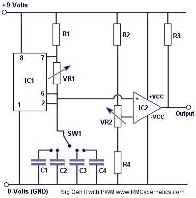
    https://www.rmcybernetics.com/scienc...gnal-generator

    Here is a simple one works good. I have a version Im turning into a Tx as well.
    Allready design its PCB with Eagle,i will give it a try later this afternoon,thanks friend!!

    Leave a comment:


  • godigit1
    replied
    Make a signal generator from easily obtainable parts. Square wave, variable frequency, variable pulse width. This can be used for many things such as DC motor speed control, lamp or LED dimming, Transformer drivers. Ignition coil circuits and other high voltage PSU's


    Here is a simple one works good. I have a version Im turning into a Tx as well.

    Leave a comment:


  • Qiaozhi
    replied
    Originally posted by mushaba View Post
    Question of the day,how does the EFE work?I imagine it takes a sample of the field,then invert it and substract it from original sample?To achieve that it should drive three op-amps one with sample another to produce the inverted sample and a third to substract them?
    The main sample will contain a signal from the target plus a contribution from the Earth field. The EFE sample is usually taken a few hundred microseconds later, when the target signal has substantially died away, whereas the EF signal will remain the same. By subtracting the EFE sample from the main sample you are then left with the target signal.

    Originally posted by green View Post
    No, preamp out from my target response tester. Don't have a MPP.
    The reason your target response tester gives a signal for the magnet is because you don't take a second (EF) sample. Of course, since the target response tester doesn't actually move, there is no need to provide this.
    This is an example of the white board magnets I'm talking about ->

    Leave a comment:


  • green
    replied
    Originally posted by mushaba View Post
    Hello green.At left of the photo the waveform is preamp out?Is it from a MPP?
    No, preamp out from my target response tester. Don't have a MPP.

    Leave a comment:


  • mushaba
    replied
    Question of the day,how does the EFE work?I imagine it takes a sample of the field,then invert it and substract it from original sample?To achieve that it should drive three op-amps one with sample another to produce the inverted sample and a third to substract them?

    Leave a comment:


  • mushaba
    replied
    Originally posted by godigit1 View Post
    HEY Mushaba,
    Going back a little bit in this thread I found this vid complete with a Scope set up and lazy mans math A online calc for checking L without a Lc meter.
    Its a way to double check ours meters as well .https://www.youtube.com/watch?v=RhS8m38ef0Y
    Hello godigit1,a function generator is on my wish list.Still a very good way,with a pulse can easily produced with a simple 555.Will try it soon .

    Leave a comment:


  • mushaba
    replied
    Hello green.At left of the photo the waveform is preamp out?Is it from a MPP?

    Leave a comment:


  • green
    replied
    Originally posted by Qiaozhi View Post
    If it "seems" to be reacting to the ground, then there's most likely some metal there (could be deep). The EFE only occurs when you wave the coil quickly from side to side. Try waving the coil in the air away from the ground, and if there's a signal at the end of each swing, the EFE is not working properly. You can also check EFE in an air test by waving a white board magnet across the coil a few inches away. Don't get too close or the material of the magnet will be detected. Air testing whether the detector reacts to ground can be done with a ferrite pot core. With default timings, the ferrite will not be detected.
    I think it was 6666 suggested using a fridge magnet. I tried one awhile back and thought it worked good, not detectable and would cause a signal when pulled away from coil. Tried one this morning, not detectable but didn't cause a signal when pulled away from coil. Tried a craft ceramic(ferrite)magnet. Thinking ferrite core and ceramic magnet not detectable as a Tx off target, lot less signal than ground(maybe none except for a shift right when coil is decaying). Target distance was adjusted for 200mV change when Tx on. Last picture is sweeping the magnet across the coil a few times. Wondering what your white board magnet is made of. Would your ferrite pot core look closer to a ground signal decay than the one I used? They would look similar to ground with a VLF.
    Attached Files

    Leave a comment:


  • godigit1
    replied
    HEY Mushaba,
    Going back a little bit in this thread I found this vid complete with a Scope set up and lazy mans math A online calc for checking L without a Lc meter.
    Its a way to double check ours meters as well .https://www.youtube.com/watch?v=RhS8m38ef0Y

    Leave a comment:


  • mushaba
    replied
    .
    Attached Files
    Last edited by mushaba; 05-05-2019, 11:31 AM. Reason: Tried 072

    Leave a comment:


  • mushaba
    replied
    Originally posted by Qiaozhi View Post
    That looks like external noise pickup. Try changing the orientation of the coil (horizontal and vertical) and see if anything changes.
    No change George..I dont have a spare NE5532 to see if there is a problem with the ic..If is an external noise pickup shouldnt show on input pin?

    Leave a comment:


  • Qiaozhi
    replied
    That looks like external noise pickup. Try changing the orientation of the coil (horizontal and vertical) and see if anything changes.

    Leave a comment:


  • mushaba
    replied
    Ok George

    Ive just came back from a field near my house,an agricaltural field sand soiled,there i realise how iron-trashy my backyard is..The detector was as suposed to be,i found some pieces of fence wire and other stuff.Came back to workshop placed detector on the air test position,calibrated the timmings frequency at 1KHZ and the first sample not before 10us and took scope readings from the Rx Preamp..First stage all looking good (to my eyes) pin2 as attached photo,pin3 at zero,pin 1 as photo (same with pin5) but at the output pin7 i think there is lot of noise,should be like that???No electrical interference near the detector

    Click image for larger version

Name:	U2 Pin2 IN-.jpg
Views:	1
Size:	364.3 KB
ID:	354037
    Click image for larger version

Name:	U2 Pin1 Out.jpg
Views:	1
Size:	355.7 KB
ID:	354038
    Click image for larger version

Name:	U2 Pin7 Out.jpg
Views:	1
Size:	381.2 KB
ID:	354039

    Leave a comment:

Working...
X