Announcement

Collapse
No announcement yet.

Let's made a PC-base metal detector with usb interface !!!

Collapse
X
 
  • Filter
  • Time
  • Show
Clear All
new posts

  • Aziz
    replied
    Dual-Frequency VLF Detector Controller Spice Files and Circuit

    Hi all,

    this is the current circuit I'm using. Below is the complete spice file (zip) and the schematics (LTspice) for your convenience.

    I think, it makes sense to route a professional PCB later (two layer).

    Cheers from "MadLabs Inc.",
    Aziz
    Attached Files

    Leave a comment:


  • Aziz
    replied
    Voltage Regulator

    Hi all,

    ok, it makes really sense to use the voltage regulator as it minimizes the drift problems due to battery voltage diminishing modulating the TX power. The diminishing effect can clearly be measured. The voltage regulator makes the software processing easier of course. Well, a good and synchronized SMPS should minimize the voltage drop power loss (for the next PI controller). But for the dual-frequency VLF detector controller, a LDO is perfect and sufficient enough (hey, it's a low-power device).

    Regarding the mosfet-driver:
    I have removed the current limitting resistor (10 Ohm) and it isn't getting even warm. Shouldn't be crititical.
    I'll try (ooops! I'm a "trial & error-engineer" ) a bipolar transistor push-pull driver just to see, if I can push more current into the coil.

    Damn it, I have a lot of harmonics!!! Darn, faaaaaaaaark! But wait! - we can just ignore the harmonics and use the two pre-defined frequencies..

    Cheers from "MadLabs Inc.",
    Aziz

    Leave a comment:


  • Aziz
    replied
    Yep, very nice!

    Hi all,

    well, I couldn't wait to see it's working. It's going to be a smart & nice Killer-App (for it's simplicity and low-power)! The transmitter is very stable with the internal H-bridge driver of the mosfet-driver this time.

    I have connected a 10 Ohms resistor between the transmitter and mosfet-driver so the mosfet driver doesn't get much hot. Well, it seems, it isn't even getting warm. I could very likely put more power to the TX coil. The total battery power consumption is almost 50 mA at 10-11 V. The TX coil voltage is approx. 35 - 40 Vpp.

    I'll watch the TX power drift due to diminishing battery voltage more deeper, whether the LDO (8.5 V voltage regulator) is necessary or not. I have made the LDO switchable active/inactive by just exchanging one jumper (see above picture).

    Oh man!, ground balancing get's quite easy with the dual-frequency VLF.

    Cheers,
    Aziz

    Leave a comment:


  • Aziz
    replied
    Dual-Frequency VLF Detector Controller finished

    Hi all,

    that's it, I just finished soldering and it is working very nice so far.
    I haven't plugged in the transmitter yet. But I have looked at the output: very clean and stable rectangular pulse so far. I had to use an audio-transformer for measurements (right inductor) to avoid power supply short-circuit due to virtual ground potential (CRO & sound-card are sharing the same earth ground line).

    When I have more time, I'll test it with the transmitter and coils.
    Cheers for now,

    Aziz
    Attached Files

    Leave a comment:


  • hdphilip
    replied
    Aziz

    nice job!


    good idea putting the resistors in a socket !


    Philip

    Leave a comment:


  • Davor
    replied
    Originally posted by Aziz View Post
    You can see the FFT spectrum "swinging" left and right
    I know, only I'm not sure whether it is a function of software or a soundcard itself.

    I used this software to learn about my soundcard performance regarding aliasing etc. I introduced a sweep from 20Hz to 20kHz and a 3D (kind of waterfall) spectrum display with linear frequency. Well, after what I've seen I am in pursuit of a better soundcard. Xonar or something.

    (artifacts are seen as a mesh of lines going everywhere)
    Attached Files

    Leave a comment:


  • Aziz
    replied
    Hi all,

    that's going to be a very nice dual-frequency detector controller (see below). Even the transmitter parts should fit into the case easily. Pity, that the parts haven't been soldered yet. I'm doing the manual placement of the parts at the moment. Why post it here? Well, if I incidental drop it, I can look how it was before.

    Cheers,
    Aziz

    PS: The second pic is showing one of my earlier prototypes (IB-PI Detector Controller V1.2 I think. I have to change the inverting pre-amp into non-inverting pre-amp yet.)
    Attached Files

    Leave a comment:


  • Aziz
    replied
    Originally posted by Davor View Post
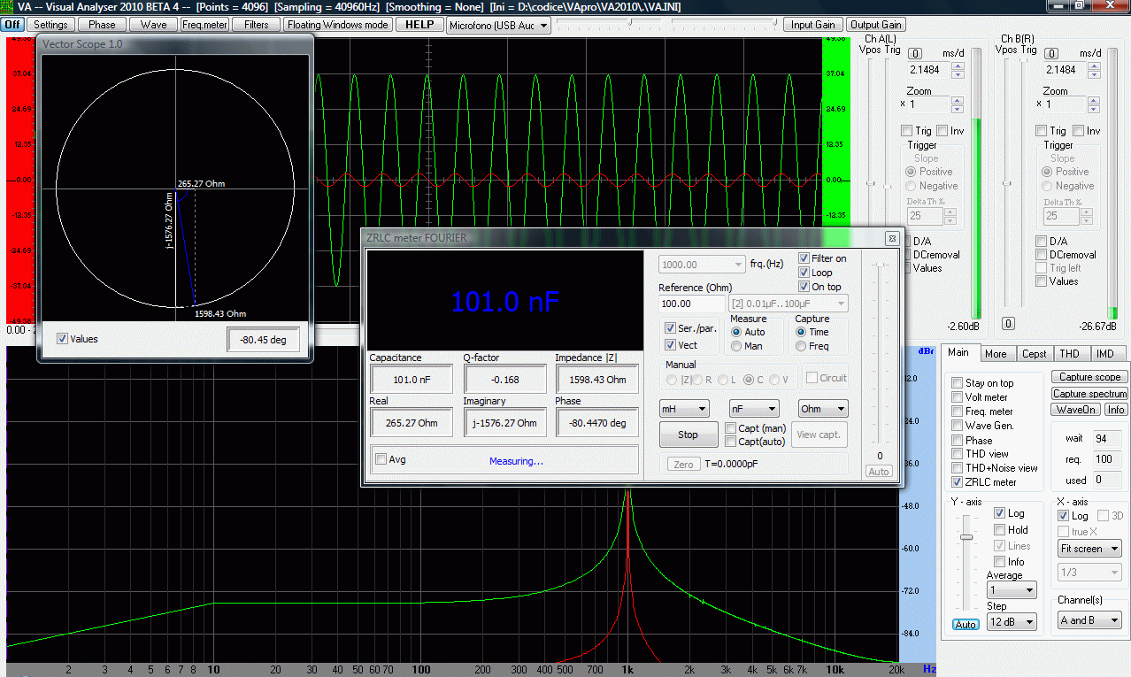
    As my oscilloscope deal failed, I had to revert to some other solutions. So I found a nice software solution that does many things using a PC soundcard. In lieu of a real oscilloscope I have this solution instead. It is a freeware called Visual Analyzer. It combines dual channel oscilloscope, spectrum analysis (including waterfall), and dual channel waveform generator. Sexy part is that it works also as a vector analyzer with a nice vectorscope circular presentation, so in essence - my PC based MD - WITH DISCRIMINATION - is already working

    Find it here: http://www.sillanumsoft.org/
    Hi Davor,

    yep, I know the software. I'm using it to measure inductors.
    But it isn't programmed well enough. You can see the FFT spectrum "swinging" left and right (spectral leakage effect due to not properly synchronising TX and RX). Even "windowing" won't help you much in this case.

    The synchronisation is one of the most important issues. When done properly, you even don't need the "windowing" of samples.

    Cheers,
    Aziz

    Leave a comment:


  • Aziz
    replied
    Originally posted by simonbaker View Post
    I'd sure like something that can measure down to 0 Hz -- don't know what's the cheapest way to do that...
    -SB
    Hi SB,

    you don't need the DC capability to measure DC or very low frequency ranges.
    You can make it similar to the chopper amplifier.
    1. Modulate your signal using a hardware modulator (DC -> AC signal conversion)
    2. Pass the modulated signal into the sound card (it's an AC signal now)
    3. Demodulate the signal back in the software

    You can measure the very small signals without the 1/f noise contribution.

    Example:
    The PI controller is such a kind of modulator. The received signals were already modulated with the TX pulse frequency. I just demodulate them back in the software.

    Cheers,
    Aziz

    Leave a comment:


  • Davor
    replied
    My criteria are very simple: it has to have two channels, and I wish it to have 20MHz bandwidth, just as the scope I just missed.
    Rigol is a cute li'l thing and I like it very much, however, for that money I can have a grown up oscilloscope with a real tube, just like the one I just missed :gah:

    BTW, the software solution I linked is capable of compensating for, say, microphone frequency response. Same thing may apply to compensating highpass soundcard input

    Leave a comment:


  • simonbaker
    replied
    Originally posted by Davor View Post
    As my oscilloscope deal failed, I had to revert to some other solutions. So I found a nice software solution that does many things using a PC soundcard. In lieu of a real oscilloscope I have this solution instead. It is a freeware called Visual Analyzer. It combines dual channel oscilloscope, spectrum analysis (including waterfall), and dual channel waveform generator. Sexy part is that it works also as a vector analyzer with a nice vectorscope circular presentation, so in essence - my PC based MD - WITH DISCRIMINATION - is already working

    Find it here: http://www.sillanumsoft.org/


    Thanks for the link. I'd sure like something that can measure down to 0 Hz -- don't know what's the cheapest way to do that...

    What will be your next hardware oscilloscope? What do you think of Rigol scopes?

    -SB

    Leave a comment:


  • Davor
    replied
    As my oscilloscope deal failed, I had to revert to some other solutions. So I found a nice software solution that does many things using a PC soundcard. In lieu of a real oscilloscope I have this solution instead. It is a freeware called Visual Analyzer. It combines dual channel oscilloscope, spectrum analysis (including waterfall), and dual channel waveform generator. Sexy part is that it works also as a vector analyzer with a nice vectorscope circular presentation, so in essence - my PC based MD - WITH DISCRIMINATION - is already working

    Find it here: http://www.sillanumsoft.org/


    Leave a comment:


  • Aziz
    replied
    Hi guys,

    I'm not satisfied with the detector controller cases I have from one supplier. But I have seen more convenient cases by other distributors. I'll split the VLF controller from the PI controller so each is optimized for its purpose.

    The VLF detector controller should fit into 80 x 50 mm PCB.
    The new PI detector controller should fit into 100 x 80 mm PCB having enough space for improvements. The case thickness should be between 30 .. 36 mm.

    Now let's finish the VLF detector controller first. That's a simple & nice application.
    Cheers,
    Aziz

    Leave a comment:


  • tjmlena
    replied
    ok

    following you

    up to soon

    Leave a comment:


  • Aziz
    replied
    Originally posted by tjmlena View Post
    Hello Aziz,

    do you think this module will help you to your project :

    http://www.ebay.es/itm/CS8416-AK4393...ht_1044wt_1125
    Hi tjmlena,

    unfortunately not! It's only a DAC and I need ADC and DAC with the same time base (same clock source). Well, (USB) sound cards are just enough, cheap and easy to drive & code.

    Aziz

    Leave a comment:

Working...
X