Announcement

Collapse
No announcement yet.

spiral pi coil

Collapse
X
 
  • Filter
  • Time
  • Show
Clear All
new posts

  • green
    replied
    Is there a specific way to test a shielded coil should I be hooking up the shield?

    The shield should be connected to one of the coil leads. Circuit common if coil is connected a circuit, if exciting resonance with another operating PI(test coil floating)connect shield to one of the test coil leads. I sometimes forget and connect the shield for a floating coil to circuit common. Less effect, not correct.

    Leave a comment:


  • bbsailor
    replied
    Originally posted by waltr View Post
    As you are starting to realize is that coil design involves many trade offs.

    Example of your Original Spool coil verse the one with added spacing.
    The spacing does reduce the C between the wires but it also enlarges the coil which decrease the L.
    To get the same L you need to increase the number of turns which then also increases the C.

    Modeling a coil for physical properties can not be done in Spice since spice uses electrical models.
    What is needed is a EM simulator that take a 3D physical model then does analysis. These EM simulators are available but the software packages are VERY expensive (several 10k's of dollars) and not simple to use.
    The best we can do is build coils and measure results.
    I would add one more part to your last sentence. The best we can do is build coils and measure results and understand the consequences on things that this relates to.

    Try using this mental model. If there was no coil capacitance, coax capacitance or circuit capacitance ,the flyback pulse would drop and not oscillate because there is no capacitance energy that needs damping. The value of the damping resistor is related to the coil energy that needs to reach near zero so the RX circuit can be turned on sooner. Typically, the energy in gold, being fully stimulated, falls to zero energy within the metal in 5 time constants. A 2uS target TC would be very hard to detect at 10uS (time delay) but at 8us could be detected. Theory tells us that to fully stimulate a target, the TX decay pulse time constant needs to be 5 times faster than the target time constant. The TX pulse TC for a 2us target would need to be 2 divided by 5 or .4uS. The TX decay TC is calculated by dividing the coil inductance by the effective damping resistor (Rd) value. A 300uH coil with a 750 ohm Rd is 0.4uS.

    As you make the coil faster you now need to ensure that the coil wire itself or anything near the coil, like a solder joint, is not being detected as a target.

    As you can see, coil design involves many tradeoffs, but understand how they interact and fit together helps understand what you need to consider to detect that low TC target.

    Joseph J. Rogowski

    Leave a comment:


  • waltr
    replied
    As you are starting to realize is that coil design involves many trade offs.

    Example of your Original Spool coil verse the one with added spacing.
    The spacing does reduce the C between the wires but it also enlarges the coil which decrease the L.
    To get the same L you need to increase the number of turns which then also increases the C.

    Modeling a coil for physical properties can not be done in Spice since spice uses electrical models.
    What is needed is a EM simulator that take a 3D physical model then does analysis. These EM simulators are available but the software packages are VERY expensive (several 10k's of dollars) and not simple to use.
    The best we can do is build coils and measure results.

    Leave a comment:


  • godigit1
    replied
    Originally posted by green View Post
    I think you will have better luck with the magnet wire especially if you added a spacing between wraps.
    Why do you think adding space between the wraps would make it better? I think spacing reduces inductance and probably increases capacitance especially if enough turns are added for the same inductance?

    Are your 3 foot leads twisted? I get about 1pf/inch when I use AWG24 twisted pair for lead. I wound a bundle coil awhile back with AWG 28magnet wire, inductance very close to calculated using the coil calculator. Calculated inductance winding the same coil with Teflon coated wire calulates about the same inductance I get winding the spiral coil using magnet wire with no spacing.

    Hi Green,
    Ive been reading so much it took me a while to find where I was getting adding spacing will reduce capacitance.
    Comes down to type of capacitance in a coil its parasitic capacitance as there is not actually two plates seperated.

    Here is a little bit of the wicki on it

    .When two conductors at different potentials are close to one another, they are affected by each other's electric field and store opposite electric charges like a capacitor. Changing the potential v between the conductors requires a current i into or out of the conductors to charge or discharge them.{\displaystyle i=C{\frac {dv}{dt}}\,}where C is the capacitance between the conductors. For example, an inductor often acts as though it includes a parallel capacitor, because of its closely spaced windings. When a potential difference exists across the coil, wires lying adjacent to each other are at different potentials. They act like the plates of a capacitor, and store charge. Any change in the voltage across the coil requires extra current to charge and discharge these small 'capacitors'. When the voltage changes only slowly, as in low-frequency circuits, the extra current is usually negligible, but when the voltage changes quickly the extra current is larger and can affect the operation of the circuit.
    Coils for high frequencies are often basket-wound to minimise parasitic capacitance.
    Effects


    I re- wound the spool coil with a layer of silicon flex tape between every five wraps it is .040mills thick.
    Both the inductance and capacitance dropped and the srf rose.
    original Spool coil
    540 uh
    588khz
    135.6pf
    Click image for larger version

Name:	20190806_181034.jpg
Views:	2
Size:	290.5 KB
ID:	354621

    spacing added
    384uh
    1.136mhz
    51.1pf
    Click image for larger version

Name:	20190807_204005.jpg
Views:	2
Size:	284.1 KB
ID:	354622

    this is the 8 coil with too much spacing notice the low voltages
    Click image for larger version

Name:	20190806_180254.jpg
Views:	1
Size:	300.8 KB
ID:	354623

    I also tested a couple other coils a 3dss
    8"
    302uh
    1.136 mhz
    64.99pf

    And the real suprise for me is a folded mono designed for the TDI
    280 uh
    500khz
    361pf
    Im thinking it has to do with the shieldind.
    Is there a specific way to test a shielded coil should I be hooking up the shield?

    So im thinking on a spiral coil the wire proximity is low as only the edges of the wires are in close proximity. (it may allready be the sweet spot)
    Im also thinking spacing added to the spiral coil will have a greater effect than some other coil types due to all the wires being on the same plane.
    what does this come down too for me?
    I think any coil design can be further optimized for capacitance by adjusting the spacing or angles that the wires may cross.
    Just building allot of the same coils to find ths out is time consuming. I wonder if there would be a way to model this as a varible in spice. Way out of my league for now.

    Thanks again for all your help and information you offer to the forum.
    And I think all the members would agree as we understand the time and effort that goes into it all.
    Best Regards.

    Leave a comment:


  • godigit1
    replied
    Originally posted by green View Post
    Litz_4, vertical coils F and H have highest signal at 5us. Litz_7, vertical coil H has lowest signal at 14inches. Think coil diameter is some of the reason, vertical coils have the smallest mean diameter. Smaller coils are better at short distances(target was close to get good signal when recording), worse at longer distances. Litz_4, vertical coils F and H come out of saturation sooner than coil B. Think coil E(Litz)is the fastest because the larger wire used in the other coils act as a target causing longer time to come out of saturation, only about 1us difference between Litz and AWG28(AWG24 longer time)made a spiral coil with AWG19 magnet wire(over 10us to come out of saturation).
    Thanks for explaining I was looking at the graph wrong realized that later after I posted.

    Started to make the verticle test coils then decided it was not practicle for the test. With the increased spacing and 28 wraps the coils would be too tall.
    Still trying to decide between flat spiral or a verticle stack 7 high 4 wide.
    Both have advantages but thinking the flat will be better for testing where the inductance is concearned.

    Leave a comment:


  • godigit1
    replied
    Hi Guys
    Ive found this calclulator useful. Solves for capacitance Freq And inductance.
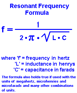
    Double checking to C= 1/(2pi*2pi*L*Srf*Srf) its been good so far.


    Have you rewraped your coil yet?
    Looking back at your photos of the first coil it does look like there are 30 wraps on just the one side of the form. If thats the case that would explaine the extra resistance on the last coil and high inductance on this coil.

    Leave a comment:


  • green
    replied
    Originally posted by sinclairuser View Post
    this calculator is quite accurate https://m0ukd.com/calculators/resona...ce-lc-circuit/

    though it requires accurate capacitance i measure the capacitance with a fluke PM6303A bench lcr meter, i also have a capacitance and esr tester i was given by one of the old boys years ago that has a magic eye valve old but still useful.
    it doesn't matter if which way you do it, it seems there are calculators out there that take different approaches to make calculations, the beauty of them is you can use the different calculators to double check the numbers.
    thanks,
    aly.
    Thanks again for the reply. Apologize for the repeats. Still trying to figure out how you can wind a spiral coil with 3.5nf capacitance. Spiral coil should be a fast coil. Looks like you are cross checking by measuring capacitance, inductance and SRF. I don't measure capacitance, but I cross check with Rd=pi*L*SRF. Our SRF and capacitance measurements are "lot" different. Do a lot of your coils measure SRF less than 200kHz? Any thoughts why SRF is so low? If you have a scope could you try measuring SRF the way I do? Clip scope ground lead to scope probe making a loop. Lay loop on the test coil, place test coil near a operating PI coil to excite resonance and read resonant decay with scope. Wondering if my procedure has a problem. Thanks

    Leave a comment:


  • sinclairuser
    replied
    Originally posted by green View Post
    How do you measure coil capacitance? I measure SRF and calculate capacitance with inductance. Looks like you measure capacitance some way and calculate SRF with inductance?
    this calculator is quite accurate https://m0ukd.com/calculators/resona...ce-lc-circuit/

    though it requires accurate capacitance i measure the capacitance with a fluke PM6303A bench lcr meter, i also have a capacitance and esr tester i was given by one of the old boys years ago that has a magic eye valve old but still useful.
    it doesn't matter if which way you do it, it seems there are calculators out there that take different approaches to make calculations, the beauty of them is you can use the different calculators to double check the numbers.
    thanks,
    aly.

    Leave a comment:


  • green
    replied
    Originally posted by sinclairuser View Post
    hi, no green 3.5nf capacitance is what the coil measures(without coil lead), as is 590uh, put in the calculator it comes to 110754.17429501114hz, but it measures 110693.162hz.
    hope that clears that up.
    like i said in the ballpark.

    aly.
    How do you measure coil capacitance? I measure SRF and calculate capacitance with inductance. Looks like you measure capacitance some way and calculate SRF with inductance?

    Leave a comment:


  • green
    replied
    Originally posted by godigit1 View Post
    Its hard to tell for me on the litz 4 graph, at the bottom where the colors all come togeteher they mingle and to me it looks llike coil B is 1 usec faster. but coil E has a faster rise time. wonder if thats partially due to the low inductance?

    As far as a magic coil no I think thats allready hear they cost 1700 Bucks. I just wanted to try adjusting coil perimeters a different way using one peice of wire length to see what the different capacitances and inductances do. Been messing with designing or moddind coils want to twist my own wire so i should learn what each varyable does, such as larger wire mass with lower inductance, Will it just slow down the coil? Who can answer that for me. I have no tutor i have to learn imperically.
    Maybe im just making nice antennas.
    Litz_4, vertical coils F and H have highest signal at 5us. Litz_7, vertical coil H has lowest signal at 14inches. Think coil diameter is some of the reason, vertical coils have the smallest mean diameter. Smaller coils are better at short distances(target was close to get good signal when recording), worse at longer distances. Litz_4, vertical coils F and H come out of saturation sooner than coil B. Think coil E(Litz)is the fastest because the larger wire used in the other coils act as a target causing longer time to come out of saturation, only about 1us difference between Litz and AWG28(AWG24 longer time)made a spiral coil with AWG19 magnet wire(over 10us to come out of saturation).

    Leave a comment:

Working...
X