
Originally posted by 6666
View Post
-
I use +-2.5 volts with my detectors. Amplifier gain=500 instead of 1000 like some other detectors. Maybe the figure8 Rx reduces the need for higher supply volts also? -
Hi Green , I see in a lot of your spice sims for PI circuits you use +- 2.5 volts on the opamps, in real life circuits do you use +- 2.5 volts or something else
does 2.5 volts give a big enough target signal to be practical ? thanksLeave a comment:
-
Few Additioal Details
Posted by: Eric Foster (---.proxy.aol.com)
Date: March 19, 2005 04:52AM
Hi bbsailor,
The 5uS is measured from the start of the transmitter switch off, so it includes the high voltage flyback time. The scope was externally triggered by the drive pulse to the Mosfet.
The shielded coil plus cable resonant frequency is 555kHz. This is measured by inducing a pulse from another coil, so it does not include any extra capacitance contribution from the electronics.
Coil inductance is 344uH and coil resistance 3.8 ohms, inclusive of cable.
The transmitter pulse is 20uS wide and the two sample pulses 5uS wide, when running at the 5uS delay. TX p.p.s. is 20,000. At the other end of the delay control, the TX is 60uS wide, with delay and samples at 15uS, and p.p.s. is 6500.
The considerable reduction in useable sample pulse delay is the sum of attention to three areas. 1) the coil 2) transmitter output and drive circuits 3) front end amplifier. At this point in time, this detector is purely experimental, just to see if the limits can be pushed out a bit further.
Eric.
Posted By KT 315 In the did I measure self resonence properly
Thanks KT 315
Hi Green,
I had a chance to do the srf test with the input resistor removed. You were right about the input resistor acting like a damping resistor. It heats up pretty fast with no damping resistor installed.
I unhooked the Input on one side and made a loop with the probe end and I get the exact same srf as I do pulsing with a live coil. The only differance is the voltage on the coil, the SRF is constant both ways. But it was good to find out this coil will still operate without a damping resistor. Coil is hitting a nickle both damped and undamped first sign at 14 inches hard by 12 its a 7" od coil not too shabby so far.
This is the SRF with the probe not touching the coil just held close.
This is the coil Undamped before I cut the input resistor.
This is the coil Damped at 2.47k measured from the fet gate.
.
I have my MPP set to 5us min sample on the delay so far this coil is more stable less chatty down that low than other coils I have tested so far.
Once I get home a settle in Ill test the other coils and some shielding see what final speed of this coil with this type of wire if spacing did anything..
ThanksLeave a comment:
-
Inside the LBT'sWhere do they hide that smoke anyway?
Hurry back your contribution has been welcomeIm going to be moving back home to NV in three days to start my fall mountain job
also I forgot to say thanks for your reply #165Leave a comment:
-
Im right with you there I think it is way easier to just excite the coil with a live pi.Originally posted by green View Post
I think there has been a misunderstanding, All of my Q calculations and SRF have been done by using a working pi and a dual field coil. Im actually taping the coil to the center of the dual field. Thats why you see the high voltage on my screen shots. I dont have a signal genny that goes over 1 meg . I want to get the rigol as it pairs with my scope but my mad money keeps getting sucked up by things like work truck repairs. I hate being my own mechanic
Ive been thinking of making one to double check The #s but I think the way we are doing it seems ok.
I have not tried any more testing since I did the first coil and had the no damping resistor in it.
I will try the loop method you have provided and see what I get. I think we will be close enough for the girls I go out with .
Im going to be moving back home to NV in three days to start my fall mountain job so ill be buried for a while I may not be able to respond in a timely manner so Im sorry for that.
I will try to get a couple more tests done before I have to tear down my workstation and pack up.
Mr Green Thank you I know Ive said that but you have helped me out emensly giving me things to think about, test procedures and evaluation and sent me off on study tangents more than once.
I must have missed the magic post I thouht it was the post where you teasingly said maybe I would find that magic coil.
So much goes over my head.
Thank you all I finally feel like im learning what I need to learn!!!!!
P.s this is all still magic to me.
and here goes the corny thing. Electricity does not make things work its the magic smoke. As soon as you let out the magic smoke no amount of electricity will get it going again. Where do they hide that smoke anyway?Leave a comment:
-
I'm still wondering if my method, laying the probe loop on the test coil and positioning the test coil near a operating PI to excite resonance isn't just as accurate as exciting test coil with a signal generator. For me it is a lot easier even if I did had a signal generator. I usually have a coil connected to my TRT circuit with the scope connected to amplifier out. All I have to do is turn TRT on and hold test coil near TRT coil and read frequency on scope. Test coil isn't connected to anything. Think getting Q measurement is ok at amplifier out but not sure. Have been using probe loop for Q measurement. I have some coils without lead or shield that measure close to 4MHz SRF that I think would have more error using the generator method.Originally posted by godigit1 View PostLeave a comment:
-
I recently built a new 3dss coil for my minipulse and I'm unsure if I measured the self resonant frequency correctly. from https://www.geotech1.com/forums/show...685#post260685 ____Appears measuring SRF isn't always easy.
I apologize for taking This is how science is done. It is not a magic belief system but something that can be replicated over and over once you understand what is going on. Accurate measurements don't lie! personal from reply #172 above. I had just suggested a different method than suggested in reply #172 a couple replies before and was thinking maybe it was magic belief. I'm learning metal detectors so I'm sure I make some measurement errors. Tried another spice simulation, closer to what bbsailor suggested. With C2 and R2 disconnected(scope probe)signal peaks at 195kHz not 988kHz with the probe. The difference errors don't matter for the SRF measurement for a PI detector. But if we want to make an accurate measurement it would be nice to know what can cause errors. Does anyone know or have a guess why SRF calculates 1MHz and measures 995kHz? Is there a reason spice could show an error when the actual measurement wouldn't have an error? Do the spice simulations need correcting?
Leave a comment:
-
Hi Green,Originally posted by green View Post
Just last night started to get stuff together for a Signal Genny.
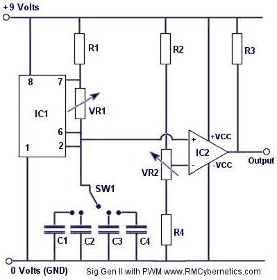
This one is comparitor based you can even run two comparators at the same time.
I currently have mine set up as Pi front end Im adding fets and damping resistor locations so it can also be used as a dual pulsing front end.
You have engineering skills I cant begin to touch Im wondering what you think of this circut as a Signal gennerator and or front end used for coil testing?
Thanks AgainLeave a comment:
-
Don't have a signal generator to compare my method with yours. Thinking of using a TLC555 to make an adjustable frequency square wave oscillator to excite coil. Tried with spice first. My method in spice, coil calculates 1MHz, circuit oscillates at 995kHz. Tried exciting coil with signal generator, coil calculates 1MHz, circuit peaks at 995kHz. What am I missing?Originally posted by bbsailor View PostLeave a comment:
-
If you can explain another method and someone else can get the same results, this is not magic. Look at how Eric Foster designed detectors more sensitive to small low TC targets by using the concepts of a "Lock-in" amplifier where multiple RX signals were integrated while the coil was over the target and many integrated samples could rise above the noise level rather than pumping more energy into the TX mode. This design concept had consequences of needing a fast PPS TX rate and controlling sweep speed to get enough samples to integrate while the coil is over the target.Originally posted by green View Post
Once you get a coil to operate at lower sampling times, the eddy currents in the wire itself, the coil shield, the coax cable solder joint to the coil wire may become unexpected targets and need a new design strategy. The more you tinker, the more you see how different and even unexpected pieces come together. If any measuring method produces repeatable results by anyone using the stated method, that is good science.
Joseph J. RogowskiLeave a comment:
-
Originally posted by bbsailor View PostThis is how science is done. It is not a magic belief system but something that can be replicated over and over once you understand what is going on. Accurate measurements don't lie!Which methods do you consider magic belief, maybe any but the one you suggested?Leave a comment:
-
Tips for measuring coil self resonance.
The output from a signal generator is typically about 50 ohms. Put a 1 meg ohm resistor between the signal generator output in series with the coil hot lead. Put the other coil lead to signal generator ground. Doing this frees the coil to easily reach resonance because the 1 million ohm resistor isolates the coil high impedance at resonance from being loaded down by the signal generator low output impedance. To keep the oscilloscope probe and leads from loading down the coils impedance at self resonance, put a 1 pF capacitor in series with the probe and the coil hot lead. Attach the probe ground to the common ground connection of the coil and signal generator. You can make a 1 pF capacitor, called a "gimmick" capacitor by twisting about 1 inch of insulated wire together and use the capacitance between the wires to again insulate the coil high impedance at self resonance from the oscilloscope probe capacitance.
Now that the coil is hooked up properly it is time to get your reading. Ensure that your signal generator can go above 1 MHz if you are trying to make fast coils with low capacitance, as your resonance may well be above 1Mhz. With the oscilloscope probe attached through the 1 pF gimmick capacitor, sweep the frequency and observe the oscilloscope screen and when you get near resonance you will see the sine waves peak. When you stop sweeping the frequency at the peak of the sine wave display, take note of the frequency on the signal generator. That is your coil's self resonant frequency and if you know the coil inductance you can go to on line electronics calculators, enter the coil inductance and resonant frequency and deduce the coil's capacitance. Keep notes of these results with each coil style, coil wire size, coil wire insulation thickness and coil wire insulation type (dielectric constant), shielding material and distance from the shield to the coil wire. Each variation will give you different capacitance levels and offer you good insight in construction techniques to reach your goals.
Just so you know what impedance range you are working in, do this calculation. Coil impedance is XL. XL = 2 pi X F (frequency) X L (coil inductance) A 300 uH coil is 300 with the decimal point moved 6 places left to get into the H range or .0003H. Now just multiply 6.28 (2 pi) X .0003 and X 1,000,000 (1MHz) and get 1,884 ohms. However, at resonance the coil impedance is very, very high due to the quality factor or Q of the coil which can be 10 to 50 times the coil impedance.
Now we are playing in the impedance range of about 19K ohms to about 94K ohms so you see how the 1 meg ohm isolation resistor and 1 pF capacitor allows the coil to do its own thing and allows you to accurately see it.
This is how science is done. It is not a magic belief system but something that can be replicated over and over once you understand what is going on. Accurate measurements don't lie! The fun part about learning is beginning to understand what is going on and how all the different things done in your latest coil design are related.
Joseph J. RogowskiLeave a comment:
-
Hi Green,
Thanks for your reply,
Im not sure how you mean to make the test loop. Do you mean just loop the probe wire?
By input resistor i think you mean the 1 k on the preamp. If I remove this will the fly back harm my amps?
ThanksLeave a comment:
-
A guess at what might be happening. MPP input resistor connects to amplifier - input, can act as Rd. I would connect the scope probe to the ground lead making a loop and hold near the coil to see if the coil damps similar to your amplifier out. Then disconnect one end of the input resistor(no damping resistor and no input resistor) to see if the coil oscillates.Originally posted by godigit1 View PostLeave a comment:
Leave a comment: