
-
Thank you Skippy. You couldn't have made repairing/replacing the plug any easier and straight forward. -
I've just had a coil in for repair, where the cable was chewed up by a pet rabbit. As well as three of the thin single-colour wires being damaged, the screened cable took a beating, and two-thirds of the screen wires were cut. It was only when I started trying to sort out the damaged screen did I discover something I had not noticed:
The screen is made from enamelled copper wire
It's just a simple lapped screen, and I guess about 30 strands. The inner core looked to be regular tinned multi-strand wire.
I grouped the 20 broken strands into 4 groups of 5 wires. The enamel burnt back easily with a soldering iron, thankfully, and each bundle of 5 was soldered to a single thicker length of ECW, formed into a small loop to give some flexibility and strain-resistance.
I've no idea how little/much my repair has compromised the performance , it's a pretty short repair, and one-third of the shield remained intact. I took it to a nearby park, and it tested fine when compared to another good coil, I'll no doubt get some feedback from the owner when he's tried it out.
I assume using 'Litz-style' screened cable would increase the speed of the cable, no doubt related to the TX signal being a square-wave of up to 40 kHz max frequency.Leave a comment:
-
Your diagram looks OK to me.
Do you have a multimeter? Here's a resistance beep-out for the other pins, which I would expect to match those of your other two coils ( though I only have the stock coil, I've not had my mitts on any others ).
Pin 7 to Pin 4 : 2000 Ohms
Pin 7 to Pin 5 : 2000 Ohms
Pin 3 to Pin 4 : 2000 Ohms
Pin 3 to Pin 5 : 2000 Ohms
These 4 are almost certainly caused by the mystery device fitted on both output from the pre-amp ( some protection part, like zeners/transzorbs etc )
Pin 4 to Pin 5 : 350 Ohms ( this is between the two outputs )
Pin 7 to Pin 3 : 3600 Ohms ( this is across the power supply, and it's probably the resistor divider network creating the virtual 'half-supply' , or it's those transient protectors things again.)
I didn't measure Pin 8, from memory it was quite high resistance.Leave a comment:
-
I don't think there's any chance you've caused damage by simply swapping Pin 1 and Pin 2 wires over, it's still the same inductance/resistance of the coil. You can check the resistance between Pin 1 and Pin on the coil connector , as you see from Post #1 it's about 0.5 Ohms.
Do the wire colours in your cable match up with those I described ? It's just possible ML have changed the cable spec, or changed the wiring, so different colours do different things?
When you broke the coil connector, was it a 'violent' snap, or something simple like one pin fell out when you unscrewed it? I'm just wondering if the coil may have been electronically damaged by the mishap. Was the machine powered up at the time the connector broke? The danger signal is Pin 1 , the main transmit signal, which is over 10 volts in magnitude, and if that connected with some of the low-voltage stuff, damage could occur.
And there's always the possibility of electrostatic damage whenever any electronics device is handled/soldered.Leave a comment:
-
I re soldered everything to the pinout and it still cycles like trying to start car but it just keeps turning over with the two bars and I can hear a click when it goes from cycle to cycle in the startupLeave a comment:
-
Do it powered OFF. It's just a short-circuit test, so in principle it won't matter... but if you power on the machine with no coil connected, it switches itself off after a few seconds anyway.Leave a comment:
-
We don't normally modify old posts without a good reason, but it makes sense to do so in this case, especially as it seems to be causing some confusion.Originally posted by Skippy View Post
I have updated post #1 in Skippy's thread with the correct pin connections to match post #10.Leave a comment:
-
I'm pretty certain my updated pinout (Post number 10 ) is correct. I have also supplied this info to another detectorist in the UK who was replacing a broken connector, and he made a successful repair.
I suggest you double-triple check the pin numbering sequence, the only pin you can't get wrong is Pin 8, in the middle. But if you're erroneously going round the outer pins in 'mirror-sequence' , you will find Pin1 and Pin 2 become swapped over.
( and to be honest, I think that is why Post 1 has the wrong info, I got the sequence mirrored. It bothers me the first post has the error ... I will contact George and see if he can edit it for me. )
Just as a confidence check, here's something simple you can test, if you have a multimeter:
Coil connector Pin 2 is the main circuit ground, and it's also the 0V ground on the USB port. If you look in the user manual, you'll see the USB port pinout, and 0V is the bottom right pin, as you look at the rear of the control pod. So a multimeter shows zero Ohms ( pretty much ) between Pin 2 and USB 0V. If you're not seeing this connection, you're perhaps probing on Pin 1 in error ?Leave a comment:
-
I need some help.
Working on replacing an equinox 800 coil plug that was damaged. I ordered a plug from Digi Key part # NOR1413-ND.
Once soldering was all completed based on the original plug pin assignment I tested it and the unit started with the two dashes on the screen on typical start up but it would cycle just doing the same two dashes flashing over and over. unscrewed it and connected it again this time it went CD error 41.
Your Pinout update suggests I have P1 and P2 reversed but that is actually what I see on the old damaged plug. I cut the original plug so that I could see the cross section that shows the red outer wire in the P1 position
Also I used shrink tube to isolate the completed soldered pins from each other instead of the hot glue fill that is in the original plug.
Pin 1 : TX cold (Shielded wire outer) Red coated copper wire
Pin 2 : TX hot (Shielded wire inner conductor)
Pin 3 : 3.3 V DC power (Brown)
Pin 4 : RX + or - (Red)
Pin 5 : RX - or + (Blue)
Pin 6 : NC ?
Pin 7 : 0 V ground (Green)
Pin 8 : Data (Yellow)
Any help would be greatly appreciated.Leave a comment:
-
Hey guys,
I just wanted to update on the latest that I was field testing and working on, as a result I have a very stable operation on max sensitivity and noticeably clearer feedback from the MD on real targets. To what it looks to me, the main improvement lies with the rejection of noise in the power lines, both Gnd and Vdc, which is primarily generated by the TX line cross talk to adjacent lines. The magnitude of the noise is quite severe, around 180mVpp on every wire that is in the coil cable, because they are wrapped around the shield of TXN (TXP is the core) - they don't cancel each other that well really. I think it is just a poor choice of otherwise unshielded unscreened cable, that is susceptible to EMI and noise. I think, ideally, ML should've shielded the twisted TXN and TXP together, similar to CAT6A network cable.
While the preamp circuit in the coil appears to be quite immune to PS noise (nor anything can be done to suppress it really due to enclosed design), the very same contaminated Vdc and Gnd lines spread back to control box and seem to have negative impact on the operation. I think ADC in use has a fairly low PSRR if I recall too. I went through a number of circuits, that included even lifting the ground and letting only the differential RX signal feed directly to the control box without ground reference, for some odd reason it elevated EMI sensitivity. The best result I could achieve is through:
- having a ground organized in a star arrangement to avoid any loops - addresses the Ground noise going into the control box.
- battery powering the Vdc line through a low noise regulation. The Vdc line from the control box is lifted and decoupled to the Ground at the star point. This eliminates the noise feeding back to the control box via Vdc.
It looks like this in the end and seems to work very well. Fits right in between the Coil and MD connection. The copper pour on the board is NC.
Leave a comment:
-
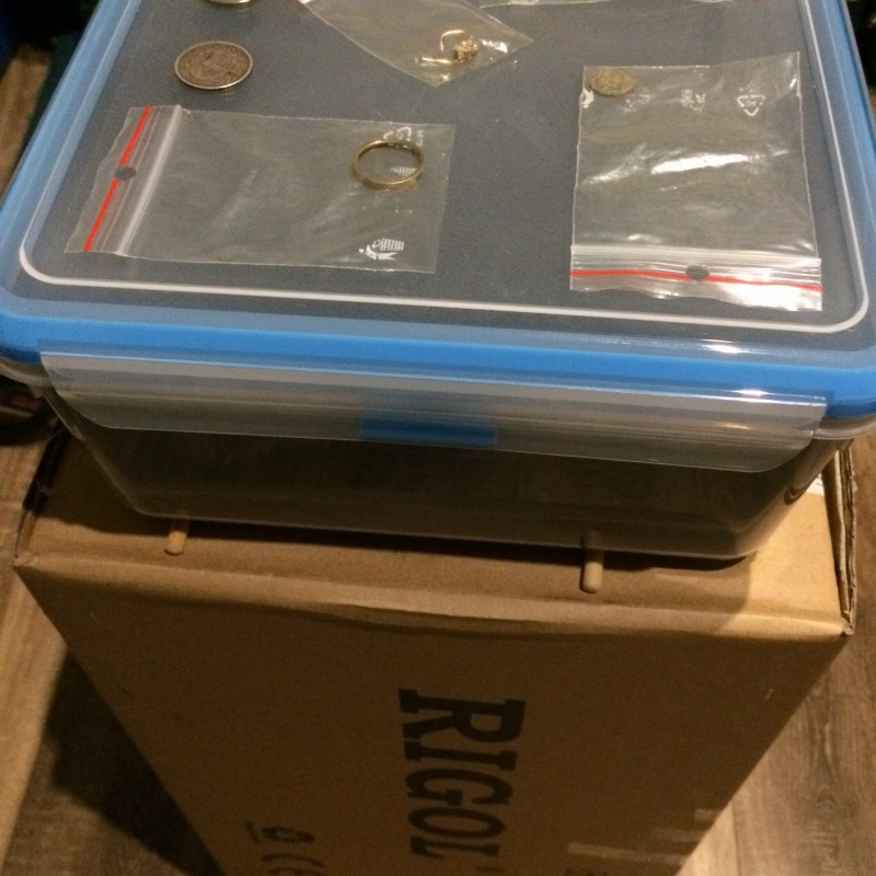
WM6 ... thank you ... Just your standard testing process on your 4-Bar Fe3O4 mineralized ceramic grit "Liapor" ... inspired me to further standardized tests for extremely strong Magnetite mineralization - type Black Sand ...
Such testing reveals many physical facts in terms of detector and coil techniques, as well as the impact of various detector settings and frequencies on the real range and also the stability of detection under conditions of heavy mineralization.
I use 3 "Black Sand" boxes with 4.4%, 12% and 33% Magnetite content to test the detectors in extreme mineralization.
Leave a comment:
-
I did an Equinox test and an 11 "coil, I used a compact Black-sand box which contains 12% magnetite.
I did a test on Park1 for multifrequency, recovery 6-7,iron bias F2=0, discriminacion =0, and sensitivity from 10 to 24.
The Ground balance on the Black Sand was the same for the multi-frequency as well as for the individual 1f frequencies and had a GB value of 2.
In another test, I have also tested Equinox on individual frequencies 5,10,15,20, a40Khz - where I have investigated how high the sensitivity is needed for a given frequency to correctly detect with IDs on various size.. and various conductive objects ..
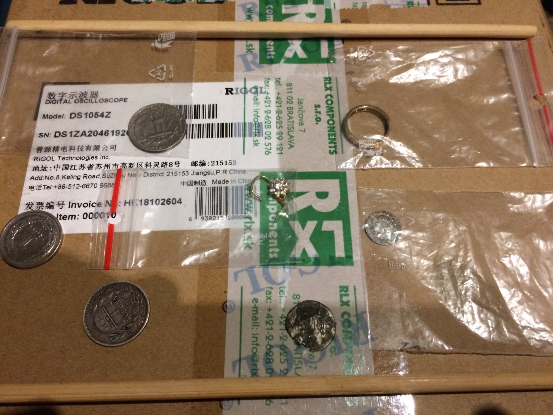
The test results are a bit of a surprise for me ... Equinox detects all objects over a 10 cm thick layer of Black Sand. on the multifrequency already at c.uz on sensitivity 12-15 .... the only exception is an open gold earring which needed a sensitivity of at least 22-23 ... and more to correctly detect...
----------------------------------------------------------------------------------------------
The biggest surprise was the direct comparison of the different frequencies on the low conductive-gold target, where it showed the advantage of having 20 and 40 kzh frequencies as opposed to 5Khz or 10 khz.
2cm -0.9gram gold ring was on 1f- 40khz detectable with ID already on sensitivity 11 ...
But when testing the ring at 1f-5khz ... I had to increase the sensitivity to at least 18 to 19 to get a similar good signal from .. ID..but from smaller detection window as it is at detection to 40khz ..
A similar but opposite situation occurred when testing Us 25cent / quarter / ...
When using 1f 5khz I got signal with ID already on sensitivity 11 ..
After changing the frequency to 40 khz, I needed to increase the sensitivity to at least 17-18 to get a similar good ID signal ... but still with a smaller detection window as it is at detection to 5Khz...
For a small open earrings you will need a sensitivity of 22-24 .. to detect it at 1 frequency of 40KHZ .. Other frequencies 5-20khz here do not have sufficient range ...
Multifrequency detects it at sensitivity 22-23 ...
At the end of the Test,... I tried to find a frequency that would have a good ID range on the high conductive Quarter .. as well as the 2cm low conductive 0.9 grams gold ring ..
As optimal frequency in this test showed 1f -15khz frequency..t but needed good detection of both objects to increase sensitivity to at least 14-15 ... Yes it is a compromise for universality ..

Leave a comment:

Leave a comment: