you can put in U1 U2:
1. both LF357
2. one TL081 another LF357
3. one LF357 another TL081
4. both TL081
-
Thank you. I want to test the LF357N.I don't understand. I need to put in the TL081 U2 together with the LF357?Leave a comment:
-
it seems good. this schematic is working just with opamp in position U1. then set another one in U2.
if LEDs HL1 HL2 are lighten then U1 and U2 are good.
you can use TL061, TL071, TL081 for U1.
pics https://www.geotech1.com/forums/album.php?albumid=109Leave a comment:
-
Hello KT315. I put photos in fotoalbum in my profile and post for verification. On recommendation, I replaced the capacitors with 25V bought and delivered LM339N.
Leave a comment:
-
hello amigoOriginally posted by jotha View Post
R7 to R13..... they are current-limited resistors for the LEDs. if you take power supply +-9V you choice one value, if +-15V you choice another value.
this is first issue. the reason is THE current you (YOU) choice.
second. opamps output is limited on level 30mA, much datasheets do not mention this value but we take this. so 15-20mA through a LED is good and standart.
10mA is safe current level, for both opamps and LEDs. it gives us middle glow for un-bright/ordinary LEDs.
for example you have 3V LEDs bright. your source is +-15V. the voltage of opamp output is 15-1 = 14V. you choice 10mA current,
(14-3)/0.01 = 1.1kOhm.Leave a comment:
-
for LM339 i added additional socket. i see LM2901 is same like LM339, one datasheet on both.
as the comparators are with 'open collectors' output you will see just one LEDs row flashing,
i did not set load resistors on outputs on board trying decrease pcb size to minimal possible. also, the checking of comparators are just an option,
but good option.
pleasureLeave a comment:
-
i do for geotechers. if they do not want to use it that is their problem. then why they ask what way to test opamps?
i sell last boards and will not return to this matter more. their unwillingness begets Unwillingness from my side to help.


Leave a comment:
-
Hi kt315
The Video was not opening for me. I thought it was no longer available.
I managed to watch the video now.
I see this op LM2901 that the pinout is also different, equal to LM339.
I'm sorry if I didn't express myself correctly.
Thank you for your information.Leave a comment:
-
hi jo
you see the video with 339 and do now want to trust of YOUR EYES??? LOL!
pin 12 connected via properties in CAD.
no mistakes. i always check all power ics' pins.
original schematic was just for opamps checking. i thought to add 339 because it used in md schematics.
you will see just half of LEDs lighten, because comparators are with 'open' output and there are not load resistors
but that's enough for the checking.
You have any video test with LM339?
first link above in your post is WITH 339.
Leave a comment:
-
Video Test
[QUOTE = kt315; 261570]
https://www.youtube.com/watch?v=-N5b8-TjuYk
https://www.youtube.com/watch?v=3S8JT0S0mmc [/ QUOTE]
Hi kt315
i have question with IC LM339... the pin 12 is -Vcc or GND ?
Wouldn't Pin 12 connect to the power GND?
You have any video test with LM339?
I Have the LM2901 too.
Best RegardsLeave a comment:
-
-
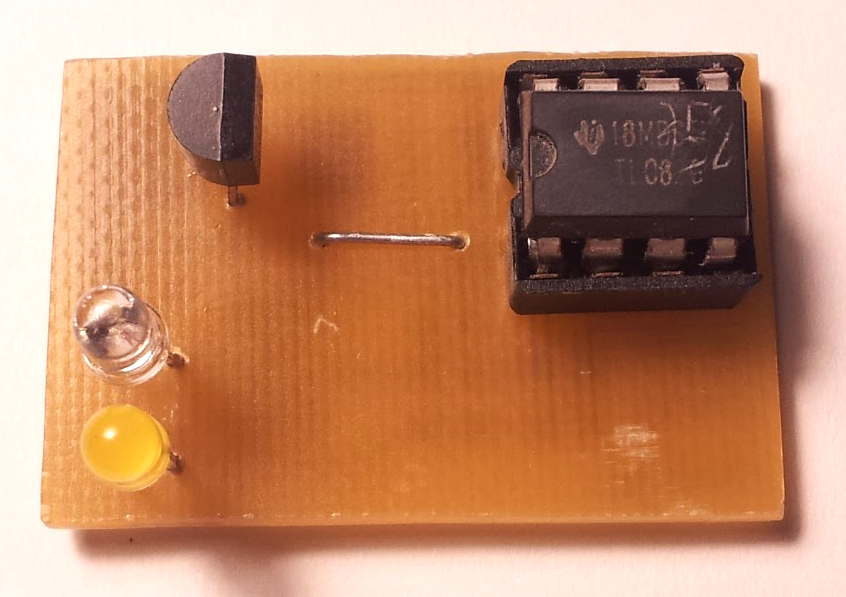
i think he set an additional cap parallel to C2. so no mistake. look on the jumper on top pcb side.Leave a comment:
-
Hi
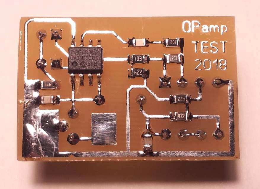
I'm assuming that Capacitor C2 was accidently misplaced on the actual PCB (it is different from the circuit drawing).
I have attached a photo of the "soldered" capacitor shown in the correct position on the PCB.
I guess that the next step would be to incorporate a socket for testing the 8-pin single J-FET op-amp LF357, which is used in many metal detector circuits,
so that they could be tested the same way for possible fakes? What about the 14-pin IC's?
Good luck all... ;-)
Leave a comment:




Leave a comment: