If this is your first visit, be sure to
check out the FAQ by clicking the
link above. You may have to register
before you can post: click the register link above to proceed. To start viewing messages,
select the forum that you want to visit from the selection below.
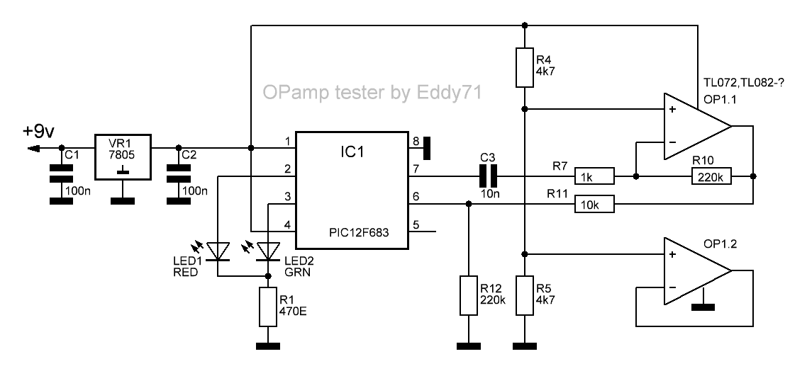
a project of Eddy71 http://www.eddy.com.ua/archives/229
simplest tester (opinion of the author) is distinguishing original TL072 TL082 vs false/remarking/fake chinese TL072.
it measures a speed of op amp.
CRY NOW CHINA! EDDY WON!
good. if LEDs light is not bright enough in your opinion increase a current decreasing resistors value.
you must not increase output max current. 10-15mA has to be good range in all cases, but learn datasheet of an op amp before testing.
also i noticed some datasheets do not have info about the max current.
Hi kt315
Yes, you offer very sound advice indeed!
Exactly what I feared, happened to me yesterday when I was testing some obscure Op Amps that I found in my junk-box.
I managed to "fry" two quad Op-Amps because I was careless.
They were:
(1) A Texas Instruments LM324N with a round indentation on one side (which I mistook for pin-1 side) and an odd 'elongated' half-moon on the other side which I thought was a trade-mark or something.
The result was that I inserted the IC the wrong way round in the OP Amp tester - there was a loud crack and flying pieces of black plastic... :-(
(2) A Texas Instruments TLC27L4CN - a CMOS quadruple operational amplifier with a max. single-supply voltage operation of 18 V (not 30 V as in the LM324N),
and an input current rating of 5 mA (not 50 mA as in the LM324N). The result of inserting this Op Amp into the Tester was that a puff of smoke was the unexpected result! ... :-(
So the moral of my story, as you have yourself insisted, is to read the DATASHEET SPECIFICATIONS of the IC FIRST before subjecting it to the Tester ... очень хорошо.
good. if LEDs light is not bright enough in your opinion increase a current decreasing resistors value.
you must not increase output max current. 10-15mA has to be good range in all cases, but learn datasheet of an op amp before testing.
also i noticed some datasheets do not have info about the max current.
The Geotech1 Op Amp Tester is based upon the March 2005 Elektor Op Amp tester.
In order to facilitate the construction of the Geotech1 version of the tester please find the dual-layer PCB tracks which helped me construct successfully this Op Amp tester, as I have previously posted here.
TOP and BOTTOM copper traces are meant for either:
(a) iron-on OR
(b) acetone-transfer purposes.
I prefer the acetone-transfer methodology and I was very successful using the 80% acetone cocktail.
I hope that this will make it easier for the amateur metal detectorists to determine the condition (good/bad) of their junk-box' comparators when thet assemble their newly-built metal detectors.
thank you for report SG. nice home work. all chinese bought LF357s are good, problem was in another place. i see doubled signal
on DD1:A and must find out a source of it. one board was sold with LF356 also chinese and the board was working good to me.
i have access just to 20MHz o-scope now, all anothers mine need repair, so i do not have a possibility to see differences in LF357s bought.
LM339 is just option. there is not mention in the original article about possibility to test the comparators.
I am about to build either the FelezJoo Pi or the PIM-5 PI metal detector.
I must still decide which one to attempt... :-(
Thanks for the very useful Op-Amp tester. I have loads of old Op-Amps in my 'junk-box'.
I have now tested most of them using the Op-Amp tester which I built for a mere €1 (including a 15 volt symmetrical power supply!).
The only difference I found with the LED lights was that a good LM339 caused the red LEDs to flash (found at the edge of the PCB) - although your 'green' LEDs were flashing (shown as yellow LEDs in your photo).
Please see my photos.
I actually found a genuine LF357 IC in my junk-box - I couldn't believe it - and it shows good although the marking have been partly ground away by some fanatical electonics engineer who had used that IC to build some
unknown electronic gadget years ago.
The National Semiconductor LF357N (M8942) features a higher slew rate and wider gain bandwidth than the others (LF355 & LF356).
The LF357N could cost as much as $2.00 each, assuming you can get your hands on one!
Keep up the good work.
Thanks again... спасибо - I did learn Russian for six months some years back... ;-)
not so big price 2 euro for board. notice i do not ask you to pay 10 euro. 4.5 euro with shipping. with board of LC tester coil board, that 2 euro too,
just 6.5 euro. so what layout, amigo? you get board from my hands directly.
i just help people and people always get new goodies from me.
can you load a picture of latest layout from opamp tester
have a package of chinese lf357 for testing and
want to make a sprint layout adaption of opampt tester
big thx
this opamp tester i did much years ago. in 86 or 87 i do not remember. it was good time of Spectrum ZX80 personal computer
we made. certainly the spekky was not original, it was Zonov's schematic. i tested some opamps before to solder in the board.
This is strange, I right clicked and saved this gif but when I view it all I see is a black square
schematic is same just i increased a current through the LEDs to approx 10mA (with +-15V supply). i looked datasheets of opamps, noted limited output op-amp current is 30mA but sometimes there are not data. so 10mA is right and no run out of the max 30mA. with +-9V supply the LEDs current will be yet low.
batch of LF357 i checked and they are OK (good way - you can check a couple at once LOL). would check them in DP now.


Leave a comment: