Announcement

Collapse
No announcement yet.

Earth Resistivity Machine

Collapse
X
 
  • Filter
  • Time
  • Show
Clear All
new posts

  • Earth Resistivity Machine

    I found a tech to help me build a resistivity machine and we have run into some problems. Would appreciate some help if anyone can.

    Heres the message he sent me to post:
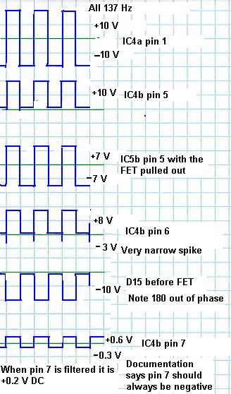
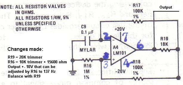
    The Eart Resistive Meter I am constructing has a problem where VR1 symmetry will not adjust on the oscillator section of the current generator. The output at pin 6 of IC1 of LM725 has only very narrow positive and negative spikess following switching. VR2 adjusts the frequency normally. Have increased the values with no change in square wave duty cycle. Would welcome suggestions as to how to correct this problem.
    Chester

  • #2
    Re: Earth Resistivity Machine

    It sounds like one of the feedback diodes (D1/D2) is backwards. If not, remove remaining circuitry by pulling D3, D4, & D15 -- this completely unloads the oscillator. If it starts working, then one of the loads is a problem. If not, check the signal at pin 2 -- it should be a triangle waveform and at low frequency should have a pretty large amplitude. If not, check C1 (bad or wrong value), or R1/VR1.

    - Carl

    Comment


    • #3
      Re: Earth Resistivity Machine

      Thank you we'll give it a try and get back with you.

      Comment


      • #4
        Re: Earth Resistivity Machine


        Is this the resistivity meter by Beck that is posted at the Geotech web site???
        If so I have it working EXCEPT for the last two stages.

        I have made some substitutions...
        Since I had trouble finding an LM725, I used a LM101 for the oscillator circuit. (I will do another post wit the attachment for this.)
        Then instead of the fast FET amps suggested I subbed TL072 and TL081.
        All seems to work and signals look good to me down to the "synchronous rectifier" (IC4b).
        I'm stuck there. My first problem is one of
        interpretation of what should be happening starting on page 7 step #5 of
        the adjustments... At this point no connection has been specified between the current generator and the receiver..... so it is pretty hard to get a signal from one to the other to make any adjustment???? I made an assumption that
        at this point C1P1 should be connected and C2P2 should be connected, as described in paragraph #6, and the 10 ohm test resistor across C1C2 .
        This makes it match an entry in table 4, page 2, of part 2. That is,10 ohm, 1mA, X100, 1V.... I set the current to 1mA since none was specified.
        Pin 1 of IC 4a has a clean square wave output of about 20V peak to peak.
        Now IC 4b is where I think I get into trouble....
        The signal after D15 is -10V, at pin 5 (IC4b) it is inverted and is at about + 8v.
        Pin 7, output, is supposed to be negative... It is about + 0.6 V square wave.
        Voltages and wave forms are in attachment....
        Thanks for any help, suggestions etc... Anyone got a 2 lb hammer*9%$#.
        Don

        --
        Window to My World: http://home.comcast.net/~dcyoung9/fpa/
        Faux-Oro, Remove SPAM to E-Mail, Have Cesium Mag. Will Travel


        Entry to my web pages...Magnetometers THing etc..

        Comment


        • #5
          Re: Earth Resistivity Machine


          John,
          I had trouble finding the LM725 so i used the attached LM101 and it seems to work OK for the
          oscillator.
          See my other post as a reply to Carl and my call
          for help as I'm stuck at IC4b. I have posted my wave forms that I believe are correct down through
          the input to IC4a.
          Don


          Pics of Lost Adams, Magnetometers, THing

          Comment


          • #6
            Re: Earth Resistivity Machine


            Is this the resistivity meter by Beck that is posted at the Geotech web site???
            If so I have it working EXCEPT for the last two stages.

            I have made some substitutions...
            Since I had trouble finding an LM725, I used a LM101 for the oscillator circuit. (I will do another post wit the attachment for this.)
            Then instead of the fast FET amps suggested I subbed TL072 and TL081.
            All seems to work and signals look good to me down to the "synchronous rectifier" (IC4b).
            I'm stuck there. My first problem is one of
            interpretation of what should be happening starting on page 7 step #5 of
            the adjustments... At this point no connection has been specified between the current generator and the receiver..... so it is pretty hard to get a signal from one to the other to make any adjustment???? I made an assumption that
            at this point C1P1 should be connected and C2P2 should be connected, as described in paragraph #6, and the 10 ohm test resistor across C1C2 .
            This makes it match an entry in table 4, page 2, of part 2. That is,10 ohm, 1mA, X100, 1V.... I set the current to 1mA since none was specified.
            Pin 1 of IC 4a has a clean square wave output of about 20V peak to peak.
            Now IC 4b is where I think I get into trouble....
            The signal after D15 is -10V, at pin 5 (IC4b) it is inverted and is at about + 8v.
            Pin 7, output, is supposed to be negative... It is about + 0.6 V square wave.
            Voltages and wave forms are in attachment....
            Thanks for any help, suggestions etc... Anyone got a 2 lb hammer*9%$#.
            Don

            --
            Window to My World: http://home.comcast.net/~dcyoung9/fpa/
            Faux-Oro, Remove SPAM to E-Mail, Have Cesium Mag. Will Travel


            Entry to my web pages...Magnetometers THing etc..

            Comment


            • #7
              Re: Earth Resistivity Machine

              to carl or anyone who could help. carl we tried everything u suggested but still have problem. im wondering if i should buy the kit for this machine to compare boards. my tech friend built ours. we might have got something wrong there. he mentioned that he thinks there were some jumpers left out of the schematic among other things. he's building another board tonight to add on to stabalize the oscillater. any help or suggestions would be appreiciated. thank's john.

              Comment

              Working...
              X