-
I realised that repetitive use may easily lead the above design to just latch, and it will need a few small corrections that involve Reset pin of CD4024, an inverter here and an inverter there. Hopefully I have a few inverters to spare, so it is going to remain simple. The automation part will remain the same. -
Nicely explained, thanks.
Really understand I do when I go play with the values and for that is a breadboard an ideal
tool.
Probably Would in practice what values need to be adjusted, I think.
Also the arrangement of the components will perhaps play a role, we'll see.
BTW I now know what you look like, and I like that when I communicate with someone.
regardsLeave a comment:
-
@Nupi, this is all my work, I have no idea when I'll be able to make it, but I'll try to make it before summer. As for calculator, I often use the simple one that comes with Windows. For any more complicated network I use spice.Leave a comment:
-
Hi,
let me explain how this automatic thing works.
When a pinpointer is powered on by depressing a pushbutton, a timer capacitor starts charging, and the voltage drifts towards the 4069 toggle point. Because of the synchronisation circuitry it will toggle somewhat earlier.
Simultaneously the integrator output voltage goes down towards a value at which the device starts beeping. It is the most sensitive at the very onset of a beep, and it is the point to which the timer is synchronised to. When the timer toggles the integrator becomes a SAH in a "hold" function, so that voltage at op amp output will remain the same for quite some time.
Because such a voltage would cause a pinpointer to beep perpetually in the air, there is a back off mechanism set by a 10k trimmer and a 220k resistor connected to a timer. When a timer toggles the control voltage is raised a little, and it thus sets the sensitivity threshold. At 1k5 at the trimmer it would continue beeping, but slowly, and at 2k2 beeping in the air vanishes, but most of the sensitivity for targets remains.
For this mechanism to work properly the timer must expire after the onset of beeps, and it may be set by the 20k trimmer. Ideally it will be 3-4 beeps before the pinpointer enters the calm phase.
I did not put any circuitry to discharge a timer capacitor faster between uses to speed up repetitive use, but it will be simple enough. A diode can do it.
Choice of FETs is critical as the VGS(off) must be below 2V. Popular types that fit the bill are 2N4393, BF245A (maybe), 2SK170 or J201. In schematic I used 2N4117, but these may be a little bit difficult to find.
I gave a thought to the choice of op amps, and it seem JFET input types without rail-to-rail capability could do if the op amp is powered from 9V. Inputs are at about 4V, and if set properly the output will never reach a lower rail, so the choice may be a bit relaxed.Leave a comment:
-
So Davor, that looks ingeniously.
Do you have use examples or Is this entirely your own work?
Anyway, great job.
I order this week the tlc271 then I can go try out.
Is there anything I should pay special attention when building?
First I'll build on my beloved breadboard.
Iam looking forward!
BTW, when are you going to try to build it, do you think?
Now that I'm still ask, My fourth and final question:
Do you know where I can find on the web a calculator thats a parallel RC network or series RC network to frequency calculating.?
I get a little tired of all this calculation.
Sorry for all the questions, but I am today in asking mood.
thanks!
Leave a comment:
-
I think I'll go for TLC271, simply because I can get them here. They go down to the lower rail (input and output), and I can put the other rail to 9V so that the positive rail is not problematic. Real rail-to-rail are still best to avoid.
What I got so far is this:
Only 2 gates of 4069 are used, so the remaining 4 may be used as a tweeter driver. It was not important for establishing the automatic circuitry, so I simply omitted them to speed up simulation.
FET can be just about any FET with pinch voltage not exceeding -2V.
10k trimmer sets sensitivity threshold, and 20k trimmer is to set the working conditions right. With its correct setting the op amp output is at about 2.5V after the pinpointer sets itself.Leave a comment:
-
You have a lot of hours in there, thank you for that.
In total, it seems like a decent not great circuit.
Maybe if the lf198 would work better, by aliexpress.com you can buy for 1,78 dollar.
I'm impatient as a child. I'm so curious how it will work. A SAH + HEX Inverter + switch,
Interestingly. Just out of curiosity,can you show us something as a schematic?Leave a comment:
-
I've got the automatic tuning working in simulation.
Now, to do it properly I'd need a cheap rail-to-rail FET input single op amp, and so far I avoided them whenever possible. In my neck of the woods they are usually difficult to obtain, and cost a lot. So far only TLC271 fits the bill, but I'm open for suggestions.
The solution uses one single op amp as an integrator/SAH, one CD4069 and a FET as a switch. So all in all it is not far off from the manual design. It also has a coarse trimmer to set the working conditions right, and a sensitivity trimmer to set, well, sensitivity threshold. I designed the whole thing based on the Colpitts oscillator for simplicity.Leave a comment:
-
Hi Harp,
The pen is completely made of plastic. It is the: edding 8400 CD / DVD / BD marker.
The lateral (side) sensitivity of the PP is 30% less than the front.
regards, nupi.Leave a comment:
-
Hello Nupi,
In the video where you presented the sensitivity of PP, you used a marker-pen with which you recorded the distance on the paper. It seems to me that this marker is in aluminum housing, all except the very top, and I noticed that your PP is not detected, even if it was very close to the coils? What is the lateral (side) sensitivity of your PP, if not a problem? Or, marker is plastic one?
Thank you!Leave a comment:
-
Hi Nezocas,
When you turn on the PP you must adjustment R1 to the maximum sensitivity.
If you search on the beach you have the PP hold a 1cm of the sand and so adjust R1 that it just not detected.
By doing this, you have the PP "ground balance" and adjusted for optimum sensitivity.
If you go under water in the sea, you must do the same. You should maybe also adjust R2.
It's a matter of trying. If you know how to do it adjust is very quickly.
You might also super tune manually, then it is even more sensitive.
But the downside is that you often have to dig very deep.
I'm a bit lazy so I'm not use that method.
regards, nupiLeave a comment:
-
Hi NUPI,
When I recived the PP from you, I did some testing with it and it only detected to 4 cm (I didnt touched the R1 and R2).
Now its up to 7 cm´s... it is very good.
I will make the 50 Km´s trip to the ocean very soon...and then report back to you.
Underwater finds will only be made with good weather.
RegardsLeave a comment:
-
You have a very nice compact and unobtrusive PP made.
I made itself seawater for testing with salt from the health food store. (see-salt)
The results were exactly the same as with the real seawater.
If you mixes masonry through you have real sea sand. Try it out!!!
The amount of salt in sea water is average 34.5 grams per kg.
That you didnt atchived the 11 cm´s detection to an european 5 cents piece may have to do with
the construction of all components together. The magnet should be as far away from the coil as possible.
The more compact you the PP make the more agitated he is. He needs space!!!
It will take some time, I think, that people get an eye for what great qualities the NUPI PP owns.
Actually I should have commercialize the PP.
I wish you lots of fun with searching.
Best regards, Nupi
nupi PP made by Nezocas
Leave a comment:
-
Hi,
Finally I had some time to finish the NUPI Pinpointer.
It ended up with a 21.5 cm long "tube" and with 3 cm in diameter.
It is fully water proof, this was all ready tested, I placed it at the bottom of a 3 meter depth swimming poll for a complete day, without no batteries inside.
I upgraded it with a reed-switch to power it on and off with a small neomagnet.
It is very stable and does not looses detection range for long periods.
When whether gets warmer it will be tested underwater at the beach hopefully finding some rings.
Lets see how it behaves in salt water.
I made a small video (turn volume up a bit) because this PP only have the vibrating motor on it.
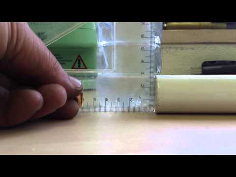
I didnt atchived the 11 cm´s detection to an european 5 cents piece (only 7.5 cm), because if I tune it up a bit the PP gets very "nervous" .... but I am very pleased with it.
In the past I wanted to buy the Vibraprobe or the Vibratector, but they are both up to 200€ .... and this pinpointer it is very cheaper to make and has got more detection range.
THANK you so much NUPI, for this great PP
Leave a comment:


Leave a comment: