Announcement

Collapse
No announcement yet.

IB Rx coil at Tx off

Collapse
X
 
  • Filter
  • Time
  • Show
Clear All
new posts

  • ZED
    replied
    Originally posted by green View Post
    I'm guessing C1 would be close to zero watts. Maybe a little do to ESR?
    Ummm what about when the coil current gets dumped into the capacitor at the end of the TX period ? My sim shows 3 amps.

    Leave a comment:


  • Altra
    replied
    Originally posted by ZED View Post
    Sweet ! & thanks green.
    Im using a 1/4 what resistor for R2 (1206),think i might need to beef it up a bit if theres 0.4 watts of power going through it.
    R1 is ok its two 1 watt 1k thin film melfs in parrellel
    D3 is a 1watt diode...hmmm.
    So would C1 be roughly 4.2 watts ?
    Don't forget voltage ratings, that's why I use higher wattage parts even if overkill. Higher wattage resistors tend to also have higher voltage rating. Less heat less noise.

    Leave a comment:


  • green
    replied
    Originally posted by ZED View Post
    Sweet ! & thanks green.
    Im using a 1/4 what resistor for R2 (1206),think i might need to beef it up a bit if theres 0.4 watts of power going through it.
    R1 is ok its two 1 watt 1k thin film melfs in parrellel
    D3 is a 1watt diode...hmmm.
    So would C1 be roughly 4.2 watts ?
    I'm guessing C1 would be close to zero watts. Maybe a little do to ESR?

    Leave a comment:


  • ZED
    replied
    Sweet ! & thanks green.
    Im using a 1/4 what resistor for R2 (1206),think i might need to beef it up a bit if theres 0.4 watts of power going through it.
    R1 is ok its two 1 watt 1k thin film melfs in parrellel
    D3 is a 1watt diode...hmmm.
    So would C1 be roughly 4.2 watts ?
    Last edited by ZED; 06-26-2020, 04:39 PM. Reason: Deleting an embarassing question

    Leave a comment:


  • green
    replied
    For practice I did Zed's sim again
    Power for Zed's sim. https://www.geotech1.com/forums/atta...7&d=1593069271
    Coil power=3.24W
    D3=2.28W
    R1=.597W
    R2=.4W
    R3=.019W
    D3 not the same as I got rely #85. Maybe I do need more practice.

    Leave a comment:


  • green
    replied
    Originally posted by ZED View Post
    Green im a bit puzzled by the zener models that LTspice has supplied and that you are using,im using a different diode and avalanching it at 200v and i get a lot more current going through it,see my sim
    Calculated coil power for your sim. =3.24W. Got 2.63W for D3, changing C1 didn't have much effect on D3 power dissipation. Just playing, learning.

    Leave a comment:


  • green
    replied
    Can get the average watts of the trace with spice. For https://www.geotech1.com/forums/atta...1&d=1593096171

    Zener watts=1.95W
    R2(R damping)=.578W
    R1=.085W
    sum=2.613W
    Coil watts(calculated)=2.64W, close to the sum [Coil power(watts)at Tx off=peak current*peak current*coil inductance*Tx pps/2]

    Leave a comment:


  • green
    replied
    Hadn't tried doing math with sim traces. An attempt to see where the power is being dissipated. Anyone see if I'm doing something wrong or missing something?
    Attached Files

    Leave a comment:


  • green
    replied
    Originally posted by ZED View Post
    Green im a bit puzzled by the zener models that LTspice has supplied and that you are using,im using a different diode and avalanching it at 200v and i get a lot more current going through it,see my sim
    R1 in my sim lowers the peak current through the Zener.

    Leave a comment:


  • green
    replied
    Originally posted by WM6 View Post
    Hi green

    Thanks for all your great efforts to visual presentation (simulations) of circuit events.

    I do not understand part of your last simulation graph.

    Can you explain a little bit, what happens to I(L1) on this graph section? Thanks.
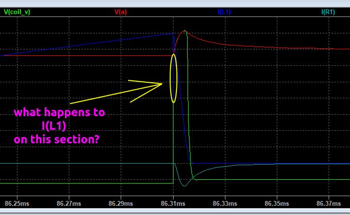

    I'm guessing you are asking about the glitch caused when coil Cpar is being charged.

    Leave a comment:


  • ZED
    replied
    Green im a bit puzzled by the zener models that LTspice has supplied and that you are using,im using a different diode and avalanching it at 200v and i get a lot more current going through it,see my sim
    Attached Files

    Leave a comment:


  • WM6
    replied
    Hi green

    Thanks for all your great efforts to visual presentation (simulations) of circuit events.

    I do not understand part of your last simulation graph.

    Can you explain a little bit, what happens to I(L1) on this graph section? Thanks.


    Leave a comment:


  • ZED
    replied
    Altra I forgot to mention,I also have a 100k resistor in parallel with the snubber cap.this drains the cap a little for the next cycle.

    Leave a comment:


  • green
    replied
    Simulation for my 30inch DD coil snubbed at 400V. 100nF capacitor looks alright.
    Attached Files

    Leave a comment:


  • Altra
    replied
    Originally posted by green View Post
    Tried a snubber in spice. The storage capacitor can be alot less than I was thinking. Not sure why yet. Maybe thinking wrong or something wrong with the simulation.

    Was thinking wrong.
    Thanks for posting the sim. From what Zed stated his low R and C values generate more heat than my higher value RC values. At some point I'll try a comparison of the two models in my circuit. The zeds version is faster acting and probably has less affect on the flyback period?

    Leave a comment:

Working...
X