-
The output of the preamp is clean, I don't think the problem is there.Originally posted by Skippy View Post
One problem this design has is that the width of the Tx pulse flickers +-200ns. The sampling delay is timed by the MCU precisely at 6.5us after the falling edge, +- 65.5 ns which is the lock cycle. However, the amplitude of the Rx signal varies accordingly. If the flicker followed a gaussian distribution then oversampling would cancel out the signal changes but if it has a 1/f distribution then it turns into low frequency noise.
One remedy is to replace the U5.A op-amp by a fast comparator. My next version will use an LM311 which has about 200ns rise/fall time. The op-amp I'm using (LM6172) has 2.5 us instead.
This disadvantage on the other hand is what makes iron discrimination possible, although at short distances (4 -5 cm). Good enough to discard trash near the surface or to stop digging or pinpointing the extracted material.
I just uploaded this video showing how this PI reacts to a gold chain.

Leave a comment:
-
I took a quick scan at the schematic. One suggestion: put low-value series resistors is the power supply to the op-amp IC's. I've no idea of precise values, that would depend on the current drain of the IC's, but 10 Ohms would be a starting point. If the resistor drops 0.1 Volt it's OK. This significantly isolates the PSU decoupling caps from the rest of the electronics, increasing their effectiveness.Leave a comment:
-
You may find this interesting. See on page 4 how a low-pass IIR may pick up resolution https://www.infineon.com/dgdl/Infine...7d0d4d0c886c92Originally posted by Carl-NC View Post
The spikes are still there.Originally posted by waltr View Post
I suspect the invalid 2 LSBs of the ADC produce codes that do not have equal probabities and oversampling and decimation cannot cancel them out. I'm going to reduce the ADC clock speed and see what happens.
EDIT: indeed, the peaks are half the amplitude by halving the ADC clock. The peak went from 100 to 50.Leave a comment:
-
Nice. Noise on scope so much better.
That is very good sensitivity to the tiny fleck of gold.
Are you still getting those random spikes or they they just much smaller.Leave a comment:
-
You're right! According to the datasheet the LM1117 regulator needs a cap with ESR < .5 ohm. I've replaced C5 on the schematic by a 47 uF cap with 0.15 ESR and the picture improved dramatically.Originally posted by waltr View Post
This is the 5V rail now.
Noise is down, I can halve the threshold. detection distance for the 0.75 g gold nugget has increased from 8.5cm to 10 cm.
It can even see this small rock embedded gold at 4cm. Delay is 5.5us. Millimeter scale.
Leave a comment:
-
started thinking of checking without coil but Carl beat me to it.Originally posted by Teleno View Post
Just saw your scope pics without coil and they do look pretty bad. I suspect there is not enough by-passing and/or bypass caps are not effective and/or
PCB layout is not as good as it should be.
Very possible the 5V regulators need better by-pass. I have seen some regulators do odd oscillations so recheck their data sheet carefully for recommended caps.
Is this noise still there if you hold the Processor in RESET? If it goes away then it is generated by the processor.
Good luckLeave a comment:
-
That's a great tip. I'll take a look at that.Originally posted by Carl-NC View Post
EDIT: Yes, the noise is still there!
The noise at the input is white. Also, the EF cancellation would do away with flicker noise present in the signal, I believe.Originally posted by Carl-NC View Post
The ADC reference is bypassed with a 100n cap to analog ground and Vanalog of the MCU is connected to Vcc by a ferrite bead.
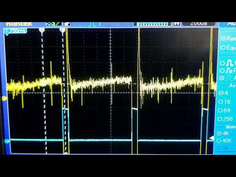
EDIT: OMG this is what the 5V rail looks like with the coil removed! A hum of about 800 Hz. I'm using 8x AAA batteries.
How can this be? Could it be an artifact of the oscope ground loop?

The baseline at the output of the preamp (AC coupled to oscope). Tee regulator is U1 in the schematic https://www.geotech1.com/forums/show...213#post295213 (sheet 1 top right).
Leave a comment:
-
My assumption is that filtering is equivalent to oversampling because it consists of adding samples. Although the samples were previously oversampled, they contain noise, so the oversampling theory also applies to the filtered samples.Originally posted by Carl-NC View Post
When you add "targetFilteredValue - (targetFilteredValue >> 6) + targetValue" the result has 6 bits more (the initial targetFilteredValue is the decimated ADC sample shifted 6 times left). After 5x tau the filter has added enough data to overcome the initial value and it's equivalent to adding 64 times the new value to the initial one (98% new value) so it has 3 more bits accuracy. From then on you get 16 bit samples with 5 tau delay plus the delay of the ring buffer.
Actually if I just do oversampling and skip filtering (or viceversa) the sensitivity drops dramatically, so I believe it's working.
The diptrace schematic isn't nice but on the same thread you have the LTSpice schematic of the analog part which is much more friendly.Leave a comment:
-
I'm not sure I understand. You get 3 bits from oversampling+filtering, but you don't get 3 bits from oversampling and another 3 bits from filtering. I suspect you have ~12 ENOBs in the end.
I assume you've disconnected the coil and the noise is still there?
Unfortunately the specs for the ADC are very minimal. But if you're getting 4mV of noise spikes at the input you should be able to see that on an oscope. If you see them at the output but not the input then look at the ADC reference.
Offhand I don't see anything in the schematic that raises a flag, but I'm not sure I understand it either.Leave a comment:
-
I appreciate your tip. I know some of you are using these ADCs and I'm sure to great advantage. I stick to an MCU because I want my PI to be minimalistic (two op-amps, two 555s an Atmega328P, two 3-pin regulators and the associated passives) and based on generic parts yet getting the most out of each part.Originally posted by KingJL View Post
It's a beautiful sunny day here in The Netherlands so I've just been to the beach in Scheveningen with a 15 bit version of the PI firmware (as above). It performed very well on a threshold of 20 - 25, better than the 16 bit version at 80 threshold. There were some random short beeps every 5 - 10 seconds but nothing bothering.
Alas, findings were mostly beer caps down to 20 cm deep (the diameter of the spiral flat coil is 15 cm, 170 uH, 1.8 A) and nails. The only coin I found (50 euro cents) was lying there in plain sight asking to be picked up. I found it because I went detecting but not with the detector )).
)).
By the way, the spiral coil combined with pitch modulation is very good at pinpointing too.Leave a comment:
-
@Teleno, not to hijack this thread or interfere with your design, have you considered the use of audio ADC's. The are (relatively when compared to other 24 bit ADC's) inexpensive and have some impressive performance specs. Mdtoday and I have been doing some design work using the 24 bit CS53xx Audio ADC's (initial design using XS5340). The oversampling frequency is ~6.5 MHz which depending on your final desired sample rate, results in oversampling factor that ranges from 32:1 to 3174:1 (initial design using 2048 sample rate resulting in 3174:1 oversampling factor).Leave a comment:
-
I am thinking your NOISE issue may be due to environment not hardware or code.
Most of us have issues with noise in our workshops with PI detectors (and other detector designs) due to the amount of EMI dues to AC Mains (including data on these lines) plus all the other electronics devices.
Try taking it outside away from all Mains and electronics to see if these noise spikes go away.Leave a comment:
-
Oversampling is based on noise in the samples having a gaussian distribution. I think when oversampling at 1000 Hz the noise below 500 Hz cannot get cancelled because it doesn't change much between samples. The flicker noise gets amplified instead.Originally posted by Qiaozhi View PostLeave a comment:

Leave a comment: