Announcement

Collapse
No announcement yet.

Signal synthesis for simple PI detector

Collapse
X
 
  • Filter
  • Time
  • Show
Clear All
new posts

  • N@SKO
    replied
    I am trying to write code for bipolar TX with PPS frequency regulation. Can I use timer0 for 2 tasks? Somеthing like task1(TX-P) ISR task2(TX-N) ISR task1(TX-P) ISR task2(TX-N).......​

    Leave a comment:


  • jafal
    replied
    Originally posted by ivconic View Post
    ...
    Thanks a lot for you

    Leave a comment:


  • jafal
    replied
    Hi

    Thanks for sharing your work

    About post #51 May this helpful flip coil
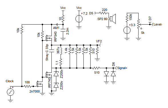

    Modelling the Flip Coil Here is a schematic based on Mirko Pavleski's Pulse Induction Metal Detector (PIMD) (https://hackaday.io/project/176291-diy-simple-sensitive-arduino-metal-detector): (Note: I think the 62k/47k output resistor divider should be moved from the inverter input of the op-amp to the output of the op-amp?). Mirko's design really appeals to me because of its simplicity. The main problem I see is that power supply is not isolated from the inductive voltage spikes from the coil. It would work with a low internal resistance battery but an electronic power supply could be a problem. There is a risk that the inductive voltage spike could be upset and/or damage the op-amp and/or the Nano. Here is Lammert Bies' PIMD (https://www.lammertbies.nl/electronics/pi-metal-detector): Here he isolated the coil from the battery using the 10R resistor and the 4m7 F capacitor. He also adds a positive power supply for the op-amp (otherwise the op-amp would be operating near its power supply voltage should DC signal processing be considered). My favourite however, is the "Flip Coil" by JorBi (https://www.instructables.com/Arduino-Based-Pulse-Induction-Detector/): Here he uses R1 to ground the negative inductive voltage side of the coil during the receive period. He also isolates the coil by


    Attached Files

    Leave a comment:


  • pito
    replied
    Almost done, PCB 80x40, and modified circuit.

    Click image for larger version

Name:	image.png
Views:	248
Size:	221.7 KB
ID:	420426 Click image for larger version

Name:	image.png
Views:	248
Size:	715.8 KB
ID:	420427​​

    Leave a comment:


  • ivconic
    replied
    ...
    Attached Files

    Leave a comment:


  • pito
    replied
    post #34, SMD not ready yet

    Leave a comment:


  • jafal
    replied
    Hi

    If you please can you post the PCB in jpeg or any other image format

    Thanks in advance

    Leave a comment:


  • pito
    replied
    @Carl-NC​
    Thanks
    Too many components there, I think circuit from post 51 will do the same job (probably better )

    Discrimination next test; Iron/Aluminium

    Leave a comment:


  • Carl-NC
    replied
    Originally posted by pito View Post
    I've been looking at the White's AF108 solution, = do you have a schematic ?

    Leave a comment:


  • pito
    replied
    I will take care of that later.

    Leave a comment:


  • Teleno
    replied
    Originally posted by pito View Post
    I would replace the existing one with bipolar using H-bridge.= maybe like this ?
    Click image for larger version

Name:	image.png
Views:	276
Size:	321.9 KB
ID:	420380​
    How is this bipolar? Both MOSFETs need to be open at the same time, no inversion of current the coil.

    Leave a comment:


  • pito
    replied
    I would replace the existing one with bipolar using H-bridge.= maybe like this ?
    Click image for larger version

Name:	image.png
Views:	276
Size:	321.9 KB
ID:	420380​

    Leave a comment:


  • pito
    replied
    I've been looking at the White's AF108 solution, = do you have a schematic ?
    This will contribute to canceling the influence of the soil mineralization, = not sure
    EFE sample is then unnecessary = EFE is for erth magnetic field not for the soil mineralization,
    The detector will require the addition of one more channel = 1 channel with seperate sample pulse.​

    Leave a comment:


  • ivconic
    replied
    Without what Joop did (ported Carl's work to AVR, so also without what Carl did the first) and without the selfless great help from Davor; I wouldn't have anything to post here.

    Leave a comment:


  • Teleno
    replied
    Originally posted by ivconic View Post
    ​
    If you think I made a deliberate mistake with the mosfet polarity symbol... you couldn't be further from the truth.
    This is not the first time. I think Moodz already pointed it out once on one of my earlier schematics.
    It's the ExpressSch software (from the ExpressPCB package) that I've been using for years to draw schematics.
    I stubbornly did not want to switch to one of the newer versions, for years I used the old version, one of the first.
    And I got into the habit of using some components incorrectly.
    In the previous post I was joking with Moodz, of course it is a serious mistake and who is off topic; he may have a problem because of that.
    But Barracuda is too well known and mentioned topic, there are many topics on the forum dedicated to that project, even the birds on the branch
    already know that P-channel mosfet is used in TX.
    The one who did not already know this and is not able to notice such a mistake by himself (there is a mosfet mark next to the symbol);
    he is not immediately ready to work with this kind of detector. Although it seems simple, it is far from easy to make.
    But I certainly accept the blame.
    Later I started using a new version of the software in which I have better done component symbols.
    And in the meantime, I myself made a lot of custom symbols for use in that software.
    That schematic still dates from before, it was not made yesterday. The forum is full of them.
    It is recommended to do the original Barracuda first and the best pcb for that is the one offered by ApBerg.
    No, really I'm not that "cunning" and I don't set "traps" in my schematics.
    All my mistakes are unintentional and accidental. And the reason for that is my laziness and inertia.
    ​
    Planting intentional errors is a form of intellectual property protection. If someone copies your stuff with the same error then you can prove a violation of your rights. Cartographers do it all the time.

    Leave a comment:

Working...
X