Announcement

Collapse
No announcement yet.

Image postings

Collapse
X
 
  • Filter
  • Time
  • Show
Clear All
new posts

  • Image postings

    This may be too little too late as it looks like the activity is rapidly fading, but I have just added a new "Post Images" option to the forum menu.


    What this gives you is the ability to upload up to 10 images in one shot. Each image can have it's own "description" directly under it, and at the very end you can add a standard message.


    - Carl

  • #2
    Re: Image postings

    Thanks Carl,


    Hopfully I'll use it. I'm still working hard on the Time Variable Gain, I got some AD605's but having a hard time getting them to work. I think my gain is to high and or the ramp votls start out to high. How do I get the ramp to start at .1 volts using a 741 op amp set up as a basic integrator with a single supply? It seems to want to start at 1.7 and go up from there.


    Tod

    Comment


    • #3
      Re: Image postings

      >Thanks Carl,


      >Hopfully I'll use it. I'm still working hard on the Time Variable Gain, I got some AD605's but having a hard time getting them to work. I think my gain is to high and or the ramp votls start out to high. How do I get the ramp to start at .1 volts using a 741 op amp set up as a basic integrator with a single supply? It seems to want to start at 1.7 and go up from there.


      >Tod


      Tod,


      Perhaps you can post your design, or at least that part around the AD605, so we can have a look.


      Who knows, someone might see the problem


      Jan

      Comment


      • #4
        Re: Image postings

        >How do I get the ramp to start at .1 volts using a 741 op amp set up as a basic integrator with a single supply? It seems to want to start at 1.7 and go up from there.


        You won't get a 741 down to 0.1v, you'll need a different opamp. I'll look around and see if I can come up with something. Let me know the following: supply voltage, starting ramp voltage, ending ramp voltage, and ramp time.


        - Carl

        Comment


        • #5
          Re: Image postings

          >>How do I get the ramp to start at .1 volts using a 741 op amp set up as a basic integrator with a single supply? It seems to want to start at 1.7 and go up from there.


          >You won't get a 741 down to 0.1v, you'll need a different opamp. I'll look around and see if I can come up with something. Let me know the following: supply voltage, starting ramp voltage, ending ramp voltage, and ramp time.


          >- Carl


          Thanks Carl,


          Supply voltage +5, starting ramp voltage +.1, ending ramp voltage +2.5, ramp time .15 sec.


          Tod

          Comment


          • #6
            Try this...


            Use the LM358. It is a single supply opamp (down to 5v) and can handle inputs and outputs all the way to 0v. Max output is 3.5v when +V=5v so that's good enough.


            Here's a little circuit I came up with that might do the trick. S1 and S2 are enhancement mode FETs that are used as switches. During normal ramp S1 is on and shorts R to ground. Current through R (and C) is 0.1v/R so ramp rate (dv/dt) is 0.1v/(R*C). To get 2.4v/0.15s we need RC=0.15/24. I used a 2.2uF cap and a 2.7K resistor with a 200 ohm trim pot in series to tweak it.


            S1 turns off when the output reaches 2.5v and stops the integration current through C. So VO will (reasonably) stay at 2.5v until we hit S2 with a reset pulse. The reset time (ts2) needs to be enough to ensure the cap discharges all the way. If you want to reset as soon as the ramp hits 2.5v then eliminate S1 (short R to ground) and use the comparator (swap the inputs) to drive S2, but you will need a turn-off delay.


            Also, you probably should take your threshold voltages off of a good reference, not the supply. I suggest a 2.5v reference (LM185/285/385) with a resistive divider to get 0.1v.


            - Carl

            Comment


            • #7
              Re: Try this...

              Thanks Carl, looks good.


              I'll get right on it and let you know how I make out.


              Tod

              Comment


              • #8
                Re: Try this...and I did


                Hi all.


                Well, I was able to find a LM2904 in my junk circuit board inventory. It seems to have about the same spec as the LM358, at least it goes to ground. I put it together just as you said Carl, and it worked fine. Then I integrated it into the AD605 variable gain amp and with a little trouble, I got that to work. Analog”s applications bulletin on the AD605 uses caps for AC coupling on VGN and Vin, I removed them and it seemed to work better. Now that I have all that, I’m not sure where to put it, and GREG, I don’t need an answer from you 
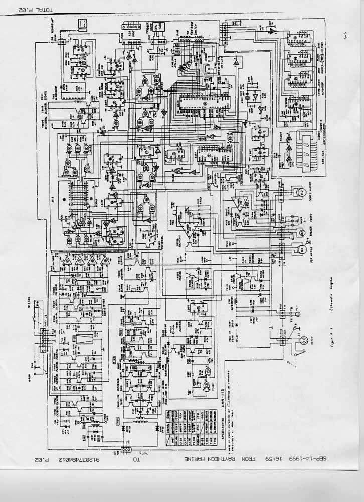
If looking at the schematic gives any one an idea on where to incorporate this ramp let me know. I can send a high res copy to any one that wants it, just email me and I’ll send it right out. Even the high res is not all that good because it was faxed to me from Raytheon and there copy is about 4 generations old.


                Thanks,


                Tod


                [email protected]

                Comment


                • #9
                  Re: Try this...and I did

                  Yikes! There's a lot of stuff in that schematic and not enough resolution. Could you mail me a good photocopy?

                  Comment

                  Working...
                  X