Announcement

Collapse
No announcement yet.

Announcement

Collapse
No announcement yet.

Need help with ill Irish PI detector....1970's vintage

Collapse
X
 
  • Filter
  • Time
  • Show
Clear All
new posts

  • Need help with ill Irish PI detector....1970's vintage


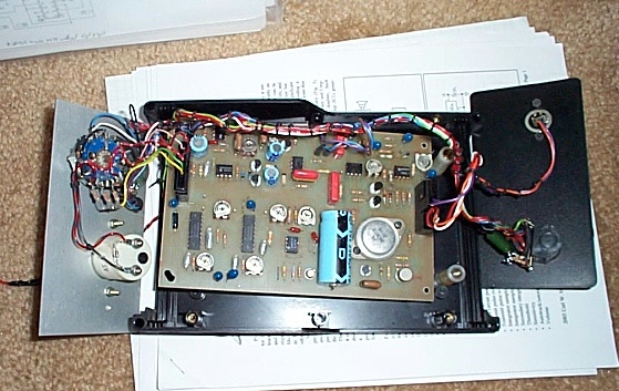
    I have an ancient Location Technology Deepscan C400 pulse detector that I would like to get running again.

    A schematic would be nice if anyone has one, or has drawn out one before.

    This model has the LM555 timer driving a PNP transistor (BC746) which drives the NPN power transistor (2n3055). Large 11" search coil. Signal is received by a 709 (pre-amp?), then divided by a 220 ohm pot to the source of twin FETs (11. The FETs are timed by a pair of 4538 ics. Signal goes to a CA3140 opamp, then to a LM741 opamp.

    I have not sorted out the audio portion yet, but see a ICM7555 timer, a 555 timer, and a pair of npn-pnp output transistors.

    Unit is powered by 8 x 1.2v nicads, and has both a 78L05 and 79L05 vr in place.
    _______________________________________________

    Unit powers up fine, and audio clicking is present when the sensitivity control (pot) attached to pin 1 & 5 of the CA3140, and pin 4 of the 709, is turned up slightly.

    No increase of signal present when even a large piece of foil is placed in front of the search coil.

    My scope tells me the LM555 timer (pin 3) is producing 83pps. This is also present on the base of the power transistor. I detect about 65 volt pulses on the collector of the 2N3055 power transistor. Pin 2 of the 709 shows the pulses...with small spikes on them. Pin 3 of the 709 just shows the pulses. Pin 6 of the 709 shows the pulses. Touching the 1x probe to pin 2 or 3 will produce a rise in the audio...promising.

    The pulses are present on pins 2 and 3 of the CA3140....indicating they are making their way through the FETS. (the timing pulses are present on the gates of the FETS)

    That is as far as I have gotten in my exam of the circuit. Any imput will be appreciated.

  • #2
    Re: Need help with ill Irish PI detector....1970's vintage

    How large are the pulses on pins 2 & 3 of the 709? If small, then check the output of the 3140 as you move metal close to the coil... you should get a DC variation.

    - Carl

    P.S. -- where are you in NC? Greensboro, here.

    Comment


    • #3
      Re: Need help with ill Irish PI detector....1970's vintage

      Hello Carl,

      I am down in Southport, NC.

      I was reading over your Hammerhead article for tips on the PI detectors; you have one page there with photos of the waveforms on a scope.

      I do notice that my output from the master clock are not sharp square pulses like you show, but look more like sawtooth pulses...slow buildup and sharp cutoff. This may effect the operation of the Tx coil? I was measuring from neg battery to pin 3 of the 555.

      My output of the preamp (709) does not resemble yours either, but again more resembles a sawtooth waveform, as do the imputs on the preamp.

      I will get a photo of these waveforms and post them for you to see. That may help you more than anything to give me some tips on this.

      Comment


      • #4
        Re: Need help with ill Irish PI detector....1970's vintage

        Try a message on the PI Detector Classroom forum. Its an Eric Foster machine and he often posts on the Classroom so might help out with the schematic.

        Comment


        • #5
          Update Tuesday PM

          Part of my problem was the Tek scope display itself. While the trace is nice and bright with good contrast, the sharp voltage pulses tend to dim out somewhat. Going back over the circuit did show 100 volt pulses on the Tx coil, and an 8 volt (square shape) pulse that measured 0.00036 sec in width on the output of the preamp.

          I have nice sharp timing pulses on the gates of the JFETs....about 8 volts positive (narrow) pulses. And of course the preamp output shows on both inputs to the two JFETS (J113....N channel silicon).

          I do not find any signal on the #2 or #3 pins (inputs) to the CA3140 (differential integrator?) I suspected the two JFETs, and changed them out with a 2n3819 and a MPF102....all I had on hand at the time.

          I was a little unsure which way to connect the source and drain of these. The originals (?) were connected with the drains to the preamp, and the sources to the integrator.

          After installing these, I got a feeble responce to aluminum foil near the coil, and was encouraged. But after perhaps 4 minutes, the responce quit??

          I do note that when my scope is set to dc for the probe, touching the probe to the #2 pin of the 3140 increases the audio quickly....touching the #3 pin decreases the audio. I feel like the circuit is fine from this point on because of this reaction.

          My question would concern the JFETs....does the source and drain connections matter?? Are either of the two replacement JFETs suitable?

          Thanks for any suggestions.

          Comment


          • #6
            Thanks Brian

            Thanks for the tip Brian. I did get some info concerning the vintage of the machine from Eric at the PI classroom. The circuit is fairly straighforward and I can work through it without the schematic.

            I see that the C400's main timer was set to run at @83 hz, with a pulse width of @400 usec. I am now using Carl's Hammerhead timer values to increase this to @900 hz with a pulse width of @35 usec

            The main and secondary sample delay and pulse width are adjustable by small pots right on the board by the two 4538 chips

            Have had some success with the machine so far in getting a responce from a square of tin foil. I think it is just a matter of setting the sample delay and sample pulse width now.

            Comment


            • #7
              Re: Update Tuesday PM

              With most MOSFETs the drain/source doesn't matter, and I believe the same is true with most JFETs. If you started getting a response with new FETs that quit after a few minutes, then I would suspect drive levels. Check the supply levels that feed the opamps and the digital, and make sure they all line up. You might have a bad regulator.

              - Carl

              Comment


              • #8
                Thanks Carl for the info

                Thanks for the reply Carl.

                I tested the two original JFETs, and they were fine. I reinstalled them. Replaced the 5 electrolytics on the board, as they must be +25 years old now.

                I replaced the timing resistors on the main 555 timer to increase the op freq to 900 pps, with a PW of 30 usec. Set the first sample delay to 28 usec with a PW of 40usec, and the second sample delay to 160 usec with a PW of 40 usec.

                The machine now has a good responce...much better than the old freq of around 90 pps.

                Comment

                Working...
                X