
 Tweet
Tweet

-
-
It came to me burned. Some "expert" tried to make battery pack different than original and probably messed something and burned several components.
I replaced these ones (yellow circles):
-
I put all the proper parts except the audio amp.
Originally it was LM4818.
I discovered that MC34119 is having the same pinout so i had it and i put it.
It works.
Difference is only in power supply, LM4818 can be supplied only with 6v (from 4 batteries directly).
That's why it was burned, the "expert" probably supplied it with higher than 6v from outer source.
While MC34119 can be supplied with wider range. So there is no problem, although now is supplied as supposed, with 6v.
I checked detector and it works alright. Everything is functioning well.
Except one thing (late on video);
When batteries are put for the first time; it can switch On on button press.
Than works alright. Than on next button press it switches Off as it should.
But than on next attempt it will not switch On on button press???
So i have to remove at least one battery from the holder, wait 4-5 seconds, return the battery and it than switch On alright.
No problems as long as it is On. When switch Off again; it will not switch On again??? Crazy!
So i have to "cut the power circle" by removing at least one battery and wait 4-5 second and than after returning the battery; it switches On alright.
I tried to measure things, tried to check components. Everything i touch; seems alright.
It was behaving the same without MC34119 on board, i tested that too. So it is not about MC34119.
What the heck is going on here on this board!?
Comment
-
Here is the schematic, pretty much alright.
It is the schematic of ACE 250.
Euro ACE is actually ACE 350, so those are similar in 90%, as far as i noticed.
Comment
-
Roughly assuming... it is like something is "charged" and stay "charged" until i remove one battery.
While it is "charged" it will not allow detector to switch On again.
So when one battery removed; the thing which is "charged" kinda "discharges" in 4-5 seconds and allows next switching On.
But what? Where? Which one? Why?
Dang!Comment
-
If it's something remaining "charged", then does it recovery if you leave it for a long time without removing the batteries?
If not, then you probably have a latch-up condition.Comment
-
Actually this is BS!Originally posted by ivconic View Post
Another BS by "flawless" ivconic!
Trick of a mind combined with exhaustion!
While writing that post i tried to recall back what actually i checked for real.
It was not MC34119 but another burned LM... from also burned ACE 250 that i have here.
So this is not correct statement. It is ABOUT MC34119 actually!
Pin1. must be unsoldered and off the board.
So i did that minute ago and problem is solved!
At LM... pin 1. is to enable the chip.
MC34119 is obviously different in that part, preventing mosfet from closing and opening properly.
I used thin needle and lifted pin 1. off the board while heathing with hot air soldering station.
So now it works alright, everything is alright.Comment
-
It is easier to see the proper wirements on this piece of schematic that i did:
Comment
-
Itching...
From MC34119 datasheet:
Chip Disable -- Digital input. A Logic ?0? (<0.8 V) sets normal operation. A logic ?1? (≥2.0 V) sets the power down
mode. Input impedance is nominally 90 kΩ.
From LM4818 datasheet:
SHUTDOWN FUNCTION
The voltage applied to the LM4818's SHUTDOWN pin controls the shutdown function. Activate micro-power
shutdown by applying VDD to the SHUTDOWN pin. When active, the LM4818's micro-power shutdown feature
turns off the amplifier's bias circuitry, reducing the supply current. The logic threshold is typically 1/2VDD. The low
0.7μA typical shutdown current is achieved by applying a voltage that is as near as VDD as possible to the
SHUTDOWN pin. A voltage that is less than VDD may increase the shutdown current. Avoid intermittent or
unexpected micro-power shutdown by ensuring that the SHUTDOWN pin is not left floating but connected to
either VDD or GND.
There are a few ways to activate micro-power shutdown. These included using a single-pole, single-throw switch,
a microcontroller, or a microprocessor. When using a switch, connect an external 10kΩ to 100kΩ pull-up resistor
between the SHUTDOWN pin and VDD. Connect the switch between the SHUTDOWN pin and ground. Select
normal amplifier operation by closing the switch. Opening the switch connects the shutdown pin to VDD through
the pull-up resistor, activating micro-power shutdown. The switch and resistor ensure that the SHUTDOWN pin
will not float. This prevents unwanted state changes. In a system with a microprocessor or a microcontroller, use
a digital output to apply the control voltage to the SHUTDOWN pin. Driving the SHUTDOWN pin with active
circuitry eliminates the pull-up resistorComment
-
Question is; will MC34119 with pin 1. not connected anywhere... but constantly connected to +6v directly from batteries; draw any current when detector is switched Off?
I tried that, switched it Off, my cheap and unreliable amper meter shows 0.00 current draw.
But i don't trust much to that amper meter.
MC34119 without enable/disable pin in circuit will always be "On".
But without input signal from MCU it obviously draws no current at all, according to amper meter.
Yet i believe it draws some at least pico amperes.
So, it will drain batteries eventually after some time, that's my assumption.
Now... good thing would be to adapt the circuitry and to return back the pin 1. to the board.
This is good for analyze...Comment
-
-
Simulation...
Code:int analogPin = 0; int val = 0; void setup() { pinMode(9, OUTPUT); digitalWrite(9, HIGH); } void loop() { val = analogRead(analogPin); if (val > 99) digitalWrite(9, LOW); }
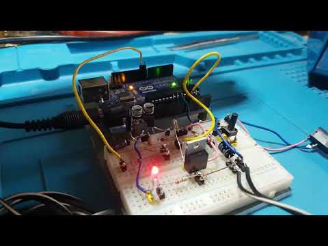
Comment
-
1uF capacitor holds the charge too short for the Arduino to initialize and startup (bootloader is present, taking some time too).
So i added 10uF in parallel... which appears to be too high, holding charge too long for fast switching Off.
So, right value is somewhere in the middle, i was too lazy to experiment further.
No harm even if it switching Off with a delay.
I just wanted to check if this will work with random components.Comment
-
As far as i managed to find:
LM4818 300-350mW
MC34119 250mW
And yet in both cases it is too loud... for Christ's sake!
Do Americans think that we are totally deaf here in Europe?
So after first part of the video; i added 10 ohms resistor in series with the speaker.
The volume hasn't changed, at least I don't hear the difference ... but the current drain is a bit less now ... at least some gain!
Watch the whole video to the end, there are some interesting moments that I didn't expect either.
It's easy to locate the GEB trimmer, so I relaxed it a bit, just enough to react to a larger ferrite rod when it's really close to the coil.
I know from experience that in real life the detector should not totally reject such a piece of ferrite.
But for the "purists", there is always the possibility that the GEB can be stretched to the limit and completely throw out this piece of ferrite.
Comment
-
The lack of volume adjustment is a serious drawback of this machine.
It sounds too loud anyway.
Except that the volume could be adjusted to a tolerable and pleasant level; also,
this option would drastically reduce consumption, which is certainly not an insignificant thing.
Now I'm sorry I didn't put more resistance in the series with the speaker , because it still sounds too loud.
And it would definitely reduce the power drain even more.
I'm tired of opening and closing the detector these days, in the end something will be damaged or spoiled by so much disassembly.
Maybe these days, if I get some new enthusiasm, I'll try with higher values of resistors, to see to what extent the current draw can be reduced.
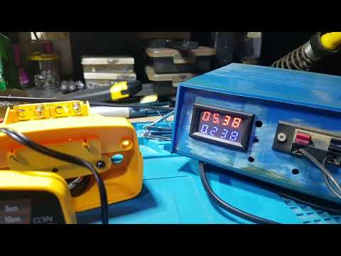
The constant consumption without sound is therefore around 70mA.
Although it should be taken with a grain of salt, I'm not too confident in the accuracy of the ampere meter.
And when it comes to clear detection; power consumption grows in peaks and over 200mA !!!
Now it is clear to me why there are some "masters" here in the region who advertise how to install rechargeable Lipo based power supply instead of original batteries.
By the default; they put one Lipo battery and additional dc/dc step up.
Or two Lipo batteries connected in series without additional dc/dc step up.
When fully charged; they give 8.4v, and while full, if frequent and strong detection occurs; of course LM4818 can't stand it and dies
and with it; it pulls the internal dc/dc, sometimes some of the mosfets and sometimes both.
That's why I've been noticing more and more broken ACE detectors lately. Some "master" had a lot of work to do!

If it is for consolation; MC34119 can stand power supply up to 16v, so the chance of such burnout is reduced.Comment
Comment