-
My project is based on the STM32H7 processor and, unlike the XP Deus, does not have an external ADC but uses an internal 16bit ADC. Here are my final PCBs which still contain small errors. I am testing the project on the original coil X35 22cm, if anyone is interested in working together on this project, we can create a special contribution on this forum. -
Hello
I am working on a Deus 2 clone project and I have an FMF coil at home and plan to open it up soon and examine the PCB which will tell us a lot about how this metal detector works.
Leave a comment:
-
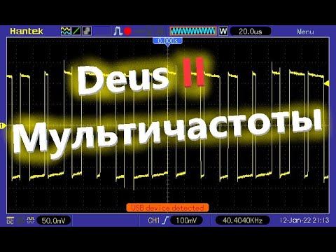
Look at this person's channel --- there are all the oscillograms for Deus. To translate into English, turn on subtitles.Leave a comment:
-
I can see them on my pc? On my ceii phone they were not visible earlier.
I think it would be more informative to scope the current and voltage at the same time. OverlaidLeave a comment:
-
I may have but it's been 4 years, so I don't recall. Here are some photos of the Park and beach mode, One photo from the detector and the other from a micro that I programmed to analyze the timing. You can see in park a 2.5khz repeat cycle. You can find the frequencies in the manual, but I doubt they give a break down for each mode.
Park 1 mode
Beach mode
Leave a comment:
-
I wired up one yesterday. It works well for a first try. I tried a TL072 and NE5532 both worked. The NE5532 seemed to be cleaner. The pickup coil is 520uh, 1 ohm. This is a nice tool for the work bench.
Equinox 800 tx current in park mode. I also tried the prospecting mode 40khz and was able to see the saw tooth current wave.
[ATTACH]n425157[/ATTACH]Leave a comment:
-
Using the current probe schematic.
Assuming the coil in the schematic is my pickup coil.
I have the following is the captured wave of:
R=
3.3 ohm
50 ohm
75 ohm
100 ohm
180 ohm
If this is wrong then the amp may not be adequate.
Leave a comment:
-
The opamp needs at least several MHz of GBW product. You might be able to get away with a TL071. The opamp needs bipolar power (say, +/- 5V). Yes, a breadboard is very useful for stuff like this.Leave a comment:
-
Okay starting from L which I'm assuming is my pickup coil.Originally posted by Carl-NC View Post
L connects to the ground probe terminal.
other L connector (my pickup coil) goes to R at 100 ohm and also feeds the inverting - input
Other end of R will connect to op amp output which also connects to the positive end of the probe.
+ input to ground clip on the probe.
Any particular op amp chip
I see now I have a very important need of a good breadboard not just a bunch of connected wires.
Hey Amazon has some cheap breadboard kits for under $20 and they usually have a power supply too.
Leave a comment:

Leave a comment: