Announcement

Collapse
No announcement yet.

Android Phone Based Metal Detector - FCMD

Collapse
X
 
  • Filter
  • Time
  • Show
Clear All
new posts

  • Carl-NC
    replied
    Originally posted by moodz View Post
    High conductivity metals maintain amplitude better at high frequencies due to skin effect:
    - High conductors (copper, silver): Ratio > 1.0 → Strong high-freq response
    - Low conductors (foil, aluminum): Ratio < 1.0 → Weak high-freq response
    ​
    In ground-balanced VLF detectors (including MF) ground is canceled by creating a "ground channel" where the demod is rotated such that the ground produces no response. In non-viscous ground this about the same phase as the R (resistive) channel so you can think of the R-channel as being the targeting channel, that is, it is the signal that causes the detector to beep. For high conductors, although the magnitude of the signal does increase with frequency, the R-channel signal increases until a phase of 135°, then it decreases. As an example, a US silver dollar (0.94 troy ounce) has a 135° frequency of ~510Hz; beyond that, as the frequency increases the R-channel signal drops and the coin gets harder to detect.

    Looking at the IQDemodulator.kt implementation, I can explain why a reference phase recovery system isn't needed in this design:

    Key Reasons:

    1. Coherent Monostatic System
    This is a coherent system where the same device both transmits AND receives. The app generates the transmit signal using MultiToneGenerator, so it has perfect knowledge of the transmitted frequencies and phases.
    ​This is true for all IB detector designs. But what, exactly, is being used as the phase reference? The TX voltage? The TX current? Something else? It has to be something, somewhere, or the whole scheme won't work.

    ​Since the demodulator runs in the same process as the transmitter, using the same sample rate and clock source, it's inherently synchronized - no PLL or carrier recovery needed.
    ​Tell AI that wasn't the question.

    3. Relative Phase is What Matters
    For metal detection, what's important is the phase shift caused by metal targets, not absolute phase. The demodulator measures phase relative to the transmitted signal. When metal distorts the electromagnetic field, it creates a phase lag that shows up in the I/Q components (lines 81-82, 96):
    ​Yes, it's a phase relative to the TX "signal". In ITMD3, I consistently use the TX magnetic field as the reference phase because, physically speaking, it's an absolute reference that does not rely on any circuit characteristics, such as coil reactance. It is 100% consistent no matter how you design the detector. And with this reference, ground is always close to 0°, magnetic targets are always 0-90°, and eddy targets are always 90-180°. Makes everything conceptually simple. If you read patents (and I'm sure AI does this) you will find that different people have used different phase systems so there is little consistency. This is bound to confuse an AI analysis of those patents.

    Originally posted by moodz View Post
    The code use "phase slope" or degrees per Khz .... so more points plotted on a graph is better than less points in most cases to determine the phase slope.
    ​Not necessarily... if all the points fall on the same line, then you could have described that line with only 2 points. And more frequencies will take away from raw depth.

    Multi-Frequency Detectors That Likely Use Similar Techniques:

    Minelab FBS/BBS Technology:
    - FBS (Full Band Spectrum) - 28 frequencies simultaneously
    - BBS (Broad Band Spectrum) - 17 frequencies
    - Multi-IQ (newer) - 5-40+ frequencies depending on model

    These definitely analyze phase response across multiple frequencies for discrimination. Minelab patents mention phase analysis, though the exact algorithm isn't published.
    ​None of these, nor any of the other MF detectors on the market, have ever used more than 3 frequencies in any given mode.

    ​What's Uncertain:

    - Whether they calculate explicit "degrees per kHz slope" like this code
    - They may use lookup tables, neural networks, or other proprietary methods
    - Exact algorithms are trade secrets worth millions in R&D
    ​
    I can tell you with certainty that "degrees per kHz slope" or something very equivalent is used.

    I think this is a very interesting project. But beware AI, I've used it and gotten a lot of wrong answers. It's important to know enough about the subject to keep it in check.

    Leave a comment:


  • moodz
    replied
    LOL ... good job !

    I asked the AI to draw a diagram of the hardware and it added a new section to the eBook with writeup and diagrams ...


    The small powered USB hub is so we can power everything and maybe add other stuff :-)

    Click image for larger version

Name:	image.png
Views:	429
Size:	98.0 KB
ID:	442325​

    Leave a comment:


  • moodz
    replied
    ... regarding frequencies also.

    20 Khz is the top tx frequency because that is the rolloff point of most "audio" usb/phone sound systems. This code will work to much higher frequencies if the rolloff is not there.

    Leave a comment:


  • moodz
    replied
    Originally posted by Altra View Post
    Studying the ebook some more. I believe that the VDI chart (9.1.1) the gold range should be above the mid conductor range targets?

    Ferrous
    Low conductors
    Gold - included in low to mid conductors
    ​​​​​​Mid conductors
    High conductors

    You could be right .. .the AI formulated all this ... the AI tends to be very confident ....maybe over confident in its designs.

    To be fair the AI does mention calibrating targets though .... and there is or was code in there to do this. ( for future implementation )

    Leave a comment:


  • moodz
    replied
    Originally posted by ivconic View Post


    A mindreader!
    Yesterday I wrote something similar to Paul via Whatsapp:


    Click image for larger version  Name:	image.png Views:	0 Size:	12.5 KB ID:	442318​
    The code use "phase slope" or degrees per Khz .... so more points plotted on a graph is better than less points in most cases to determine the phase slope.

    Multi-Frequency Detectors That Likely Use Similar Techniques:

    Minelab FBS/BBS Technology:
    - FBS (Full Band Spectrum) - 28 frequencies simultaneously
    - BBS (Broad Band Spectrum) - 17 frequencies
    - Multi-IQ (newer) - 5-40+ frequencies depending on model

    These definitely analyze phase response across multiple frequencies for discrimination. Minelab patents mention phase analysis, though the exact algorithm isn't published.

    XP Deus Series:
    - Multi-frequency capable (4-40+ kHz range)
    - Uses phase information for target ID
    - Allows frequency offset analysis

    Whites Electronics (now defunct, acquired):
    - V3i had three-frequency correlation
    - Showed separate VDI readings per frequency
    - Users could observe phase/response differences

    What I Know For Sure:

    1. VDI scales (0-99) are industry standard - used by Garrett, Whites, Fisher, etc.
    2. Phase discrimination is well-established physics:
    - Referenced in academic papers on induction metal detection
    - Ferrous vs non-ferrous discrimination via phase lag is documented
    3. Multi-frequency discrimination is proven superior to single-frequency for target ID

    What's Uncertain:

    - Whether they calculate explicit "degrees per kHz slope" like this code
    - They may use lookup tables, neural networks, or other proprietary methods
    - Exact algorithms are trade secrets worth millions in R&D
    ​

    Leave a comment:


  • moodz
    replied
    Originally posted by Carl-NC View Post
    Couple of items...

    Running so many frequencies so close together doesn't buy anything and will cost you depth. A 3:1 ratio is about the minimum useful spacing so I would do 3 frequencies at, say, Tones 1, 5, and 8.

    I never saw a phase reference stated anywhere so I don't know where the target phases are coming from. Ferinstance, the examples in 9.2.1 make no sense to me. You absolutely have to have a reference or you won't know where ground is at.
    Yep .. regarding the tones : I did allow for 2 to 24 tones ... user selectable ... the default is 8.

    1. Target Discrimination (Primary Benefit)

    Different metals respond differently across the frequency spectrum. The VDI Calculator uses this to identify target types:

    Phase Slope Analysis (VDICalculator.kt:85-96):
    // Calculate phase slope across frequencies
    val phaseDiff = highest.phaseDegrees() - lowest.phaseDegrees()
    val freqDiff = highest.frequency - lowest.frequency
    return phaseDiff / (freqDiff / 1000.0) // degrees per kHz

    - Ferrous metals (iron, steel): Steep negative phase slope (< -3°/kHz) → VDI 0-30
    - Non-ferrous metals (copper, gold, aluminum): Flat or positive slope → VDI 30-99

    This is impossible with a single frequency - you need at least two frequencies to measure a slope.

    2. Conductivity Index (VDICalculator.kt:102-117)

    High conductivity metals maintain amplitude better at high frequencies due to skin effect:

    val lowFreqAmp = analysis.take(analysis.size / 3).map { it.amplitude }.average()
    val highFreqAmp = analysis.takeLast(analysis.size / 3).map { it.amplitude }.average()
    val ratio = highFreqAmp / lowFreqAmp

    - High conductors (copper, silver): Ratio > 1.0 → Strong high-freq response
    - Low conductors (foil, aluminum): Ratio < 1.0 → Weak high-freq response

    This helps distinguish copper (VDI 70-99) from aluminum (VDI 40-50).

    3. Depth Estimation (DepthEstimator.kt:120-134)

    Deep targets preferentially attenuate high frequencies:

    val freqRatio = lowFreqAmp / highFreqAmp
    // ratio > 1.5 indicates deep target (high freqs absorbed more)

    This helps disambiguate "large shallow" vs "small deep" targets, though it's still challenging.

    4. Confidence Scoring (VDICalculator.kt:123-136)

    Multiple frequencies enable phase consistency checks:

    val phases = analysis.map { it.phaseDegrees() }
    val stdDev = calculateStandardDeviation(phases)
    val consistency = 1.0 - (stdDev / 90.0) // 0-1 score

    If phase varies wildly across frequencies → Low confidence (noisy/unstable target)
    If phase is consistent → High confidence (solid target)

    5. Reduced False Positives

    A single frequency might miss targets or give false alarms. With 8-24 frequencies:
    - Ferrous rejection is more reliable (need steep slope across ALL frequencies)
    - Gold vs aluminum separation improves (though still challenging)
    - Ground mineralization affects frequencies differently, so multi-freq helps cancel it

    Trade-offs

    More frequencies = Better discrimination BUT:
    - Higher CPU usage (24 IQ demodulators running)
    - More transmit power spread across frequencies
    - Longer processing time

    The app defaults to 8 logarithmically-spaced tones (1-20 kHz) as a good balance between discrimination power and performance.

    Bottom line: Single frequency = "There's metal here"
    Multi-frequency = "That's a copper penny at 4 inches with 85% confidence"
    ------------------------------------------------------------------------------------------------------
    ------------------------------------------------------------------------------------------------------

    Regarding phase reference : ​

    Looking at the IQDemodulator.kt implementation, I can explain why a reference phase recovery system isn't needed in this design:

    Key Reasons:

    1. Coherent Monostatic System
    This is a coherent system where the same device both transmits AND receives. The app generates the transmit signal using MultiToneGenerator, so it has perfect knowledge of the transmitted
    frequencies and phases.

    2. Direct Phase Knowledge
    In SingleToneDemodulator (line 68-69), the local oscillator phase is directly tracked:
    private var phase = 0.0
    private val phaseIncrement = 2.0 * PI * frequency / sampleRate

    Since the demodulator runs in the same process as the transmitter, using the same sample rate and clock source, it's inherently synchronized - no PLL or carrier recovery needed.

    3. Relative Phase is What Matters
    For metal detection, what's important is the phase shift caused by metal targets, not absolute phase. The demodulator measures phase relative to the transmitted signal. When metal distorts the
    electromagnetic field, it creates a phase lag that shows up in the I/Q components (lines 81-82, 96):

    val i = sample * cos(phase)
    val q = -sample * sin(phase)
    val phaseAngle = atan2(qFiltered, iFiltered)

    4. Contrast with Traditional Radio Systems
    In a typical radio receiver:
    - Remote transmitter with unknown frequency drift
    - Unknown carrier phase
    - Requires PLL/Costas loop/carrier recovery

    But here, the transmitter and receiver share the same clock and are perfectly synchronized by design.

    The ground balance system (GroundBalanceManager.kt) captures baseline I/Q vectors to cancel soil
    effects, but that's different from phase synchronization - it's removing unwanted target-like responses from mineralized ground.


    The AI "dev team" answered your questions here.

    I would have basically said the same but less words and maybe no references.

    I had a very good discussion with the AI in the early stages of this project .... it seemed to have a very clear idea of how a Minelab multi IQ detector works and showed me code to match ... so one would infer it has seen / been trained on code from that source
    ​

    Leave a comment:


  • ivconic
    replied
    Originally posted by Carl-NC View Post
    Couple of items...

    Running so many frequencies so close together doesn't buy anything and will cost you depth. A 3:1 ratio is about the minimum useful spacing so I would do 3 frequencies at, say, Tones 1, 5, and 8.

    I never saw a phase reference stated anywhere so I don't know where the target phases are coming from. Ferinstance, the examples in 9.2.1 make no sense to me. You absolutely have to have a reference or you won't know where ground is at.


    A mindreader!
    Yesterday I wrote something similar to Paul via Whatsapp:


    Click image for larger version

Name:	image.png
Views:	439
Size:	12.5 KB
ID:	442318​

    Leave a comment:


  • Altra
    replied
    Studying the ebook some more. I believe that the VDI chart (9.1.1) the gold range should be above the mid conductor range targets?

    Ferrous
    Low conductors
    Gold - included in low to mid conductors
    ​​​​​​Mid conductors
    High conductors


    Leave a comment:


  • Carl-NC
    replied
    Couple of items...

    Running so many frequencies so close together doesn't buy anything and will cost you depth. A 3:1 ratio is about the minimum useful spacing so I would do 3 frequencies at, say, Tones 1, 5, and 8.

    I never saw a phase reference stated anywhere so I don't know where the target phases are coming from. Ferinstance, the examples in 9.2.1 make no sense to me. You absolutely have to have a reference or you won't know where ground is at.

    Leave a comment:


  • Altra
    replied
    Originally posted by moodz View Post

    I will let the "dev team" answer your question - they are more eloquent than I am :

    ● Great questions! Let me answer both based on section 8.2 of the ebook:

    1. Is t = 1/fs?

    Not exactly. In the continuous-time equations, t represents continuous time in seconds. However, in the discrete implementation, samples occur at intervals of Δt = 1/fs.

    Looking at the implementation in IQDemodulator.kt:918:
    private val phaseIncrement = 2.0 * PI * frequency / sampleRate

    For each sample n, the time is t_n = n/fs, so the phase becomes:
    phase(n) = 2π * f * (n/fs) = (2π * f / fs) * n

    This is why phaseIncrement is calculated as 2π * f / fs - it's the phase change per sample, where each sample represents a time step of 1/fs.

    2. Is this mixer basically a single bin DFT?

    Yes, exactly! This is functionally equivalent to computing a single frequency bin of the Discrete Fourier Transform.

    The DFT for frequency bin k is:
    X[k] = Σ x[n] * e^(-j*2πkn/N) = Σ x[n] * (cos(2πkn/N) - j*sin(2πkn/N))

    Breaking into real and imaginary parts:
    - Real part: Σ x[n] * cos(2πkn/N) → This is the I component
    - Imaginary part: Σ x[n] * sin(2πkn/N) → This is the Q component

    The key differences from a standard DFT:

    1. Filtering approach: Instead of summing over a fixed window (N samples), it uses a single-pole IIR low-pass filter (α=0.01) that acts as an exponentially-weighted moving average
    2. Continuous operation: Runs sample-by-sample in real-time rather than on blocks
    3. Computational efficiency: Maintains a running phase rather than recalculating trig functions

    As explained in section 8.2.1, after low-pass filtering, you extract:
    - Amplitude: √(I² + Q²) * 2 (the ×2 compensates for the factor of 1/2 from mixing)
    - Phase: atan2(Q, I)

    So yes, it's a streaming, single-bin DFT optimized for real-time metal detection!
    Many thanks to your team for the concise reply. Carl describes this method in his latest book as a digital "narrow band demodulator".
    Last edited by Altra; 11-09-2025, 09:48 PM.

    Leave a comment:


  • ivconic
    replied
    Because of this:

    Click image for larger version

Name:	Meche.jpg
Views:	1298
Size:	489.8 KB
ID:	442300

    I am now forced to do this:

    ​

    Leave a comment:


  • ivconic
    replied
    "...All that remains is to assemble the small TX drive..."

    Dang!
    Sleeping Beauty occupied my workspace, if I tried anything; I will get very sharp claws!


    Click image for larger version

Name:	IMG_0886.jpg
Views:	1319
Size:	677.1 KB
ID:	442297​

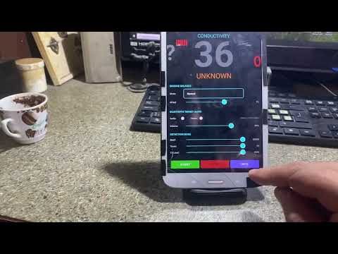
    That's why I put off making the TX drive and decided to test the APK on some oldies I still have!
    Never throw away old devices!
    This Samsung Galaxy Tab 3 was once used by Jesus... and now by me!
    I installed LineageOS to extend its life.


    Click image for larger version

Name:	IMG_0888.jpg
Views:	1294
Size:	776.8 KB
ID:	442298​
    And it's really crazy interesting to test a new apk on a very old device.
    And ... it WORKS!


    My congratulations to the author!
    This is immediate proof of excellent programming (I had no doubts)!
    The next device to test is the CAT S60... but the battery is dead so I'll do that later.

    ​

    Leave a comment:


  • ivconic
    replied
    Speaking of UI... you'll probably disagree Paul, but a twisted mind like me has the idea to adapt the UI to the XP Deus look!


    Part of the functionality to move to ESP32 and make the coil "wireless"!
    I don't know if I will succeed, there are too many obligations and too little time, the winter days are short, there is too much on my shoulders.
    But... a port to Python opens up possibilities for further development and experimentation on multiple platforms.
    I personally don't like Python, I consider it a bad and weak derivative of C++ language.
    But it is the fastest and easiest for jobs when you don't have a lot of time.
    I have a couple of older smartphones that have a CTIA (AHJ) jack and it won't be a problem to try your original code.
    All that remains is to assemble the small TX drive. I have some stock coils, worth testing them.
    ​

    Leave a comment:


  • ivconic
    replied
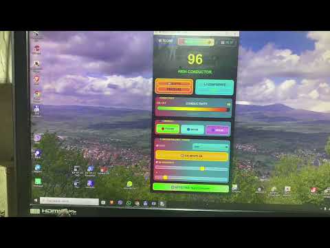
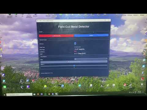
    Trying to port it... some functionalities are subject to add soon:

    Leave a comment:


  • ivconic
    replied

    Leave a comment:

Working...
X