 Tweet
Tweet
This could be a bit easier to build no pesky varicaps
-
-
BFOs are usually constructed with small coils because it increases the stability. Although I have seen one with a 32" coil!Originally posted by Beach View Post
That's probably the easiest method to use. You can use the Coil Calculator here ->Originally posted by Beach View Post
to determine the number of windings required.
Simply jumble-wind the coil. In other words, find a saucepan (or something similar) of the correct diameter and wind the required number of turns around the bottom. There is no need to neatness. Then remove the coil and apply some insulation tape to hold it secure. You may also need to apply an electrostatic shield to prevent coupling the ground. After that, fix the coil to a suitable base.Originally posted by Beach View PostComment
-
I would suggest building it according to the article and get that working first so you have a known reference point for when you want to make changes like a larger coil.Originally posted by Beach View Post
As to the length of you step, that has nothing to do with metal detecting. To have success, you need to go slow and overlap your swings a lot. Remember the diameter of the area in which you can detect an object 6 inches down is much smaller than the diameter of the coil at the surface.
JerryComment
-
-
And SPICE shows the incompetent designed operating point:Originally posted by mikebg View PostComment
-
OK, now I am a bit confused. Does this mean the circuit is good or not good?Originally posted by mikebg View Post
Thanks!Comment
-
Thanks Jerry! This is what I will try first. Kind of like baby steps before running.Originally posted by Jerry View PostComment
-
OK, as advised I am proceeding as per the Hageman schematic. Once it is finished then I will try to make what ever adjustments or corrections I can.
Today I wound my first search coil!!!
As advised I looked around my kitchen and found a souffle bowl that was almost 4 inches. The coil ended up to be 4.25 inches. It is 16 winds of 22 AWG magnet wire.

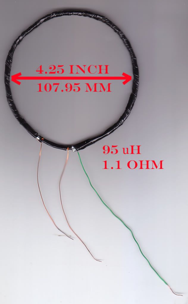
Once wound, I wrapped it with electrical (insulating) tape.
I then wrapped it in aluminum foil tape almost all the way around leaving about a 1 inch gap.
I then applied a single strand of copper wire to the top of the coil and gave it another cover of electrical tape.
I then checked for continuity between the foil and the end of the copper lead and it was fine.
So now on to the second coil.
As advised by Carl, I will endeavor to wind my next coil to 95 uH to match the search coil, but here is where I need help.
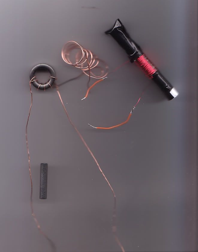
What is the best way to wind and mount this coil? Below are some samples of what types of coils and ferrite I have to work with. Any help would be deeply appreciated!

Thanks again!Comment
-
If you use the ferrite rod, you can adjust the inductance by sliding the coil along the length of the rod. Maximum inductance should occur in the middle.Originally posted by Beach View PostComment
-
OK, please let me know if this sounds like it would work.Originally posted by Qiaozhi View Post
If I wrap a pencil with a few wraps of paper. Wind 30 AWG wire around the paper. Remove the pencil and then insert the small ferrite rod from the picture into the paper and wire cylinder until the uH matches the 95 uH search coil.
Does that sound like it will work?
Thanks!Comment
-
-
Hi Mike,Originally posted by mikebg View Post
It's not uncommon for oscillators to have a strange (or unsolvable) DC operating point.
- CarlComment
-
Hi Carl,Originally posted by Carl-NC View Post
I know that you (and most participants of this forum) are not radio amateur designers. Ham designers know that the transistor oscillator is an amplifier with enough high gain. It is absolutely incopetent to design operating point of such amplifier near to transistor saturation, because the gain is minimall and (if oscillation starts) the circuit can not deliver enough amplitude.
However you are correct for the opposite operating point. Then the self-bias makes transistor to amplify in class C and the amplitude of oscillation is largest.Comment
-
The technique you described would work, but the problem is going to be determining the number of turns required. This will need some experimentation.Originally posted by Beach View Post
The designer probably used a standard RF choke, such as these -> http://uk.farnell.com/jsp/search/bro...D2031%2B202745Comment
-
Murphy’s rule when paraphrased for oscillators reads:Originally posted by Beach View Post
“Amplifiers will oscillate but oscillators won’t.”
The following link is for a paper
"Analysis of Common-Collector Colpitts Oscillator"

Note that there is no information how to design the operating point of transistor for reliable start of oscillation and for large amplitude (because the author is not radio amateur :-).Comment
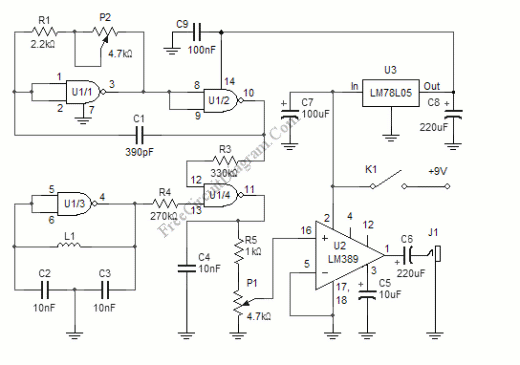
 ) but I want to make the search coil larger then 4 inches because my steps are longer then 4 inches. Around where I do most of my detecting, 6 inches into the dry sand is deep enough. Anything deeper then that is usually an old beer can.

Comment