Hello,
Ive finished the Arduino VDI. I have a proplem. Upload examples as HelloWorld work fine. But uploading the MD_V13 programm shows encoder errors. For example "Encoder.cpp:102: error: `ms´ was not declared in this scope.
What does that mean??? Have anyone an idea?
Regards
Prospekteur
-
VDI Arduino project I2C version of LiquidCrystal library
There were questions about the missing I2C LCD lib.
Here is LiquidCrystal_I2C.zip library used by the VDI Arduino project. It is required to the I2C LCD to work.
To install it extract the zip (preserving dirs) to Arduino's library directory; (C:\Program Files (x86)\Arduino\libraries on my system)
There maybe a newer versions of it on the web. This is the one that was used with the project.
LiquidCrystal_I2C.zip
DarenLeave a comment:
-
Chuckle. It is impressive. currently trying to wrap my head around the PIC24FJGC006 for a project. Way overkill for a VDI, but looks like I should be able to do a minimal part device with it, since it has two built inOriginally posted by golfnut View Post
opamps, 3 comparators, a 12 bit 10 million samples a second ADC. But boy, it is a complex bugger. Started trying to get one up Friday. I *really* need my wirewrap tool, but don't know where it is.Leave a comment:
-
@Prospekteur: I'm not sure what PCB you are referring to, I assume its opamp board as all others are "off the shelf"; I will look if I have a picture of the bottom side that I built; I know I have top (already posted). I have the board glued into the box, so I can't take it out.. If I find it I'll post it in few days (away from home now....)Leave a comment:
-
Hello,
can everyone post (or send pm to me) pictures from both sides of the ready build pcb for the arduino?Leave a comment:
-
craftsmen primarily for sharing such nice information thanks to you all I want to do and for that matter I audion VDI have no idea which version do you recommend to me and my country if I share a site should get an audion and help the lcd, and audion and how it should be done, and the lcd is most effectively wave circuit how do I link already thenks...?
http://www.direnc.net/ARDUINO-URUNLERI,LA_1281-2.html#labels=1282-2
Leave a comment:
-
This all good stuff, fairly sure it will go onto any simple 2 ch machine, idx
I would have liked to be able to code better, Im just not wired that way, I think in pictures and write in crayon
Leave a comment:
-
The one thing I did not see in the zip file, is how the encoder hooks up. Where is that defined in the code? It isn't in the encoder.h file, which is where I assumed it would be.
I think it would be nice to have a complete schematic. One of the things I've been toying with is that it seems to me that you could save the X and Y data, then run through it 3 times. One searching for the maximum X and maximum y, the minimum X and minimum Y and use those two end points to compute the phase angle. Since most of these signals look like a quashed loop on the scope, scanning the X array, looking for the maximum value BEFORE the end point, and scanning the array, looking for a maximum value before the end point, should allow you to compute two more angles. One would be the upper phase range, and the lower phase range, so you would perhaps get a +71 for the main vector, and a +66 and a +78, as an example, for bounding ranges, and thus derive a phase angle range. This could then be run through a simple fuzzy inference engine to get a quite accurate description.
Fuzzy logic is ideal for these kind of things. It basically expresses a set of rules as functions of a trapezoid, establishes the amount of membership (essentially the percentage that the item is within one range, and the percentage it is in a second range, then defuzzifies it to a crisp value. It is NOT A PERCENTAGE however. The concept is kind of hard to grasp, but it is very powerful for these sorts of problems. If the angle is above x and below y, and it is a bit more to the left of center than it is to the right then the probability of it being a nickle is xxx and a tab is xxx.
http://en.wikipedia.org/wiki/Fuzzy_logic this is a good explanation. Phase angles and metal identification fall neatly into this kind of a scheme.
substitute pennies, dimes and quarters for cold warm and hot, and the range of each on the x axis, is the phase angle range read from the meter to get an idea of what I am proposing here.
It is essential to realize that fuzzy logic uses truth degrees as a mathematical model of the vagueness phenomenon while probability is a mathematical model of ignorance. Applying truth values[edit]
A basic application might characterize subranges of a continuous variable. For instance, a temperature measurement for anti-lock brakes might have several separate membership functions defining particular temperature ranges needed to control the brakes properly. Each function maps the same temperature value to a truth value in the 0 to 1 range. These truth values can then be used to determine how the brakes should be controlled.
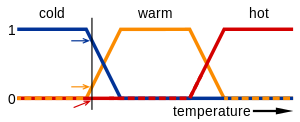 Fuzzy logic temperature
In this image, the meanings of the expressions cold, warm, and hot are represented by functions mapping a temperature scale. A point on that scale has three "truth values"—one for each of the three functions. The vertical line in the image represents a particular temperature that the three arrows (truth values) gauge. Since the red arrow points to zero, this temperature may be interpreted as "not hot". The orange arrow (pointing at 0.2) may describe it as "slightly warm" and the blue arrow (pointing at 0. "fairly cold".
Leave a comment:
-
Thanks Daren, drop me a pm, and I'll give you my email. I have some ideas to make this vdi even niftier. Problem is I don't do arduino or C++, so I'll have to recast it into C. I have an LCD library I wrote for the 8051. I'd like to find the source for all libraries used. I write embedded code for a living, pure Keil 8051 C. I predefine 5 characters for custom characters, but where I would like to have a graph, the user defined characters are not used. Never occurred to me to rewrite them on the fly like this, but after analyzing the code, and removing the in-line variable declarations it makes perfect sense.
There is one question though. The data is an array of 40 character 0 to 7. and they are unsigned. Not sure why you are assigning them to an integer, but testing for <0 doesn't make any sense on an 8051. Unsigned by defintion, especially if the values are only 0 to 7, means that they are positive. So a test for <0 and then assign it to 0 doesn't seem to make sense, even if there might be a possibility of bad data. Me, I'd just do data[n] & 0x07; which will make sure the values are ONLY in the range of 0-7.
Been bit way to many times by comparing signed to unsigned, and a <= is a signed compare....
I think I'd rather see a realtime clock, then the battery, or else show the battery for 1 second every 30 seconds or so, and the time the rest of the time.
The device I develop programs for happens to use a 2 x 12 display, and an Silabs 8051F040, so I have my own 4 bit interface code for the LCD, which includes writing characters, strings, lines, and screens, as well as programming custom character codes. The other things that I feel would be really useful would be the x phase reading, the Y phase reading and the G reading.
(note I have whites 4900 and 5900's. The 4900 I want to put a VDI on. The 5900 already has a VDI.) And I am fixing to build an IDX and perhaps a TSGL. Fitting stuff into 12 characters is
a challenge.
zz ppp XX:XX ppp =+/-xx phase
sss ggggggg
zz = zk (zinc) cp (copper penny) (ni) nickle dm (dime) qr (quarter) gd (gold) sv (silver) pt (pop tab) ir (iron) XX:XX time of day SSS signal strength and gggggg the graph.
diag display
zz ppp xx:xx
gnd yyy xxxx gnd= ground reading yyy = y reading xxx= reading
http://www.ebay.com/itm/like/231352091016?lpid=82 a current link to the device I write code for. Not sure how it is getting on ebay.... that is a prescription device...
I basically want to port the code over to this device, since I have a bunch of engineering versions that can't be sold, and a few cases.. All for my own use.
I'll be glad to contribute the code back to this thread though.Leave a comment:
-
scrungy_doolittle: if you are referring to the graph on the 16x2 LCD here is the relevant code:Originally posted by scrungy_doolittle View Post
m_lcd is Arduino's LiquidCrystal_I2C or LiquidCrystal library object
(BTW: all code for this project is posted in this thread: post #116
16x2 allows for 8 custom characters; they are used to create graphics
//data: array of 40 values 0 to 7
void CVDILcd::lcdGraph(int row, int column, unsigned char data[40])
{
unsigned char b[8][8] = {{0}};
for(int n=0;n<40;n++)
{
int h = data[n];
if(h>7) h=7;
if(h<0) h=0;
int c = n/5;
int pc = 4-n%5;
for(int r=7;r>=(7-h);r--)
{
b[c][r] |= 1<<pc;
}
}
for(int n=0;n<8;n++)
{
m_lcd->createChar(n, b[n]);
}
m_lcd->setCursor(row, column);
for(int n=0;n<8;n++)
{
m_lcd->write(n);
}
}Leave a comment:
-
The two comments yesterday were on the original code that Don posted..... Just for the record. The latest code is pretty sweet.
I try to avoid floating point in micros, because it is rather slow, but that is because I use 8051's even if they are running at 24 MHz, with a core that has 1 clock per byte of instruction, for most instructions, and runs with 40 ns clock.
I work with Silabs F040. 64K flash, 4 k ram, nice adc/dacs, (but I don't use them). We produce a damped sinusoidal waveform that swings from about +500v to -500 v at nano amps at the maximum, using a flyback transformer. This is used to supply stimulation pulses for an electronic pain killer. Much like a PI detector. The ringing is damped by the capacitance and resistance of the skin, and we use that to measure changes to the body.... I'm thinking the same technique might be used for a PI detector. The lower the conductivity, the narrower the signal.Leave a comment:




Leave a comment: