-
I don't understand, file order does not matter. Just make sure they are all listed in the project.Leave a comment:
-
Hi, Carl, how should the BipolarPI source code be arranged? I do it like this, but it gives me an error that it cannot find common.h. I also tried manually specifying the folder. What advice would you give me? Thanks.
Leave a comment:
-
Ah, that's a code-writing artifact that I haven't removed.
I forgot it.
The initial code had more functions.
Now it has only 2 modes of operation: "Gen" and "Sweep".
But the idea was to test the oscilloscope and not the generator.Leave a comment:
-
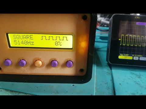
Zero percent's of what? The software some times gives slightly strange massages at first view.Leave a comment:
-
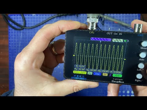
I assume the "hiccup" on the oscillogram is due to the USB power supply.
I didn't feel like checking because it's good enough as it is.Leave a comment:
-
For code readability I used Cpp directives.
However, in the final version it is preferable to replace them with direct port&pin manipulation.
Because the execution speed will be higher than 12x to even 40x !!!
I plan to do that in the final version once everything else is checked and set up.Leave a comment:
-
Ok, until I get the pcbs from JLPCB, no reason not to try porting the code.
In the previous attempt, I did some things badly.
Now I already have a working version.
All that remains is to precisely set the time.
The matter is more complicated because a potentiometer was also introduced to adjust the frequency.
The code works. But it's still not tweaked to run the H-Bridge safely without risk.
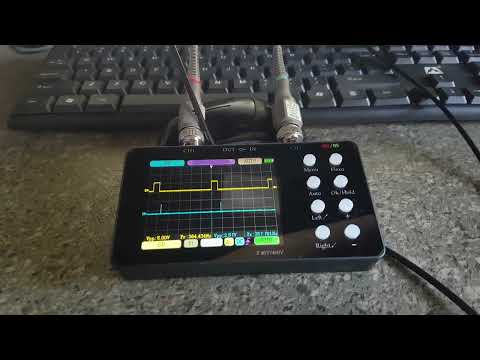
The main problem I have is the lack of a multi-channel oscilloscope (the 10k and pulse merging trick doesn't work very well, due to overlapping critical times).
Currently, the frequency can be adjusted from 600Hz to 3kHz. But any change in frequency will affect the timing.
(Perhaps introducing frequency change was a bad idea but it is a tempting challenge)
It is recommended to test the code on the Arduino UNO platform without the rest of the hardware.
Colleagues who have multi-channel oscilloscopes; can help a lot here!
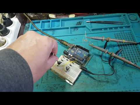
Code:/* * Bipolar PI metal detector by Carl Moreland * Ported from PIC16F18426 implementation */ #define TX_P_PIN 2 // Transmit positive pulse pin #define TX_N_PIN 3 // Transmit negative pulse pin #define CP_SYNC_PIN 4 // Charge pump sync pin #define TGT_P_PIN 5 // Target sample positive pin #define TGT_N_PIN 6 // Target sample negative pin #define GND_P_PIN 7 // Ground sample positive pin #define GND_N_PIN 8 // Ground sample negative pin #define POT1_PIN A0 // Potentiometer 1 (delay) pin #define POT2_PIN A1 // Potentiometer 2 (frequency) pin // Constants #define POT_AVE 8 // Number of samples to average for potentiometer readings #define POT_SHIFT 3 // Shift value for averaging (divide by 8) #define ON HIGH #define OFF LOW #define TRUE 1 #define FALSE 0 // Timing parameters (in microseconds, scaled by 8 in settings) struct AppSettings { uint16_t txPeriod; // TX pulse period (200-1000 μs) uint16_t txWidth; // TX pulse width (50-200 μs) uint16_t tgtDelay; // Target sample delay (10-30 μs) uint16_t tgtWidth; // Target sample pulse width (20-60 μs) uint16_t gndDelay; // Ground sample delay (5-20 μs) uint16_t gndWidth; // Ground sample pulse width (20-60 μs) } settings; // Timing values calculated from settings struct TimingStruct { uint16_t txWidth; uint16_t cpWidth; uint16_t txDelay; uint16_t tgtDelay; uint16_t tgtWidth; uint16_t gndDelay; uint16_t gndWidth; } timing; // ADC variables uint16_t pot1Array[POT_AVE]; // Running average array for pot1 (delay) int8_t pot1Index; // Current index in pot1Array uint16_t pot1Total; // Total of values in pot1Array uint8_t pot1Value; // Current averaged pot1 value uint16_t pot2Array[POT_AVE]; // Running average array for pot2 (frequency) int8_t pot2Index; // Current index in pot2Array uint16_t pot2Total; // Total of values in pot2Array uint8_t pot2Value; // Current averaged pot2 value // Interrupt state volatile uint8_t intState = 0; volatile uint8_t polarity = 1; // Function prototypes void initSettings(); void initTimers(); void updateTiming(); bool adcRun(); bool getPot1(); bool getPot2(); void clearSignals(); // Timer1 Compare Match A ISR ISR(TIMER1_COMPA_vect) { // Reset the counter TCNT1 = 0; switch(intState) { case 0: // Start of a new TX Pulse OCR1A = timing.txWidth; // Set next compare for TX width if(polarity == 0) digitalWrite(TX_P_PIN, ON); // Turn on P-side MOSFET else digitalWrite(TX_N_PIN, ON); // Turn on N-side MOSFET intState++; break; case 1: // Falling edge of the TX pulse OCR1A = timing.tgtDelay; // Set next compare for target delay digitalWrite(TX_P_PIN, OFF); // Turn off TX pins digitalWrite(TX_N_PIN, OFF); digitalWrite(CP_SYNC_PIN, ON); // Toggle charge pump clock intState++; break; case 2: // Start of Target sample OCR1A = timing.tgtWidth; // Set next compare for target width if(polarity == 1) digitalWrite(TGT_P_PIN, ON); // Turn on target sample else digitalWrite(TGT_N_PIN, ON); intState++; break; case 3: // End of Target sample OCR1A = timing.gndDelay; // Set next compare for ground delay digitalWrite(TGT_P_PIN, OFF); // Turn off target sample pins digitalWrite(TGT_N_PIN, OFF); intState++; break; case 4: // Start of Ground sample OCR1A = timing.gndWidth; // Set next compare for ground width if(polarity == 1) digitalWrite(GND_P_PIN, ON); // Turn on ground sample else digitalWrite(GND_N_PIN, ON); intState++; break; case 5: // End of Ground sample OCR1A = timing.cpWidth; // Set next compare for CP width digitalWrite(GND_P_PIN, OFF); // Turn off ground sample pins digitalWrite(GND_N_PIN, OFF); intState++; break; case 6: // Before next cycle OCR1A = timing.txDelay; // Set next compare for TX delay digitalWrite(CP_SYNC_PIN, OFF); // Toggle charge pump clock intState = 0; polarity = !polarity; // Flip polarity for next cycle break; } } void setup() { pinMode(TX_P_PIN, OUTPUT); pinMode(TX_N_PIN, OUTPUT); pinMode(CP_SYNC_PIN, OUTPUT); pinMode(TGT_P_PIN, OUTPUT); pinMode(TGT_N_PIN, OUTPUT); pinMode(GND_P_PIN, OUTPUT); pinMode(GND_N_PIN, OUTPUT); digitalWrite(TX_P_PIN, OFF); digitalWrite(TX_N_PIN, OFF); digitalWrite(CP_SYNC_PIN, OFF); digitalWrite(TGT_P_PIN, OFF); digitalWrite(TGT_N_PIN, OFF); digitalWrite(GND_P_PIN, OFF); digitalWrite(GND_N_PIN, OFF); analogReference(DEFAULT); // default 5V reference // Clear ADC signals clearSignals(); // Initialize settings with default values initSettings(); // Calculate initial timing values updateTiming(); // Initialize timers initTimers(); } void loop() { static bool adcFlag = false; // Single flag for ADC state if(intState == 1) { // Idle state if(!adcFlag) { if(adcRun()) // Read pots and update if values changed updateTiming(); adcFlag = true; // Mark ADC as checked } } else { adcFlag = false; // Reset flag when not in idle } } void initSettings() { // Initialize timing settings (all in μs, scaled by 8) settings.txPeriod = 200 << 3; // 200μs -> 5kHz settings.txWidth = 50 << 3; // 50μs settings.tgtDelay = 15 << 3; // 15μs settings.tgtWidth = 10 << 3; // 10μs settings.gndDelay = 5 << 3; // 5μs settings.gndWidth = 40 << 3; // 40μs } void initTimers() { // Stop interrupts while setting up noInterrupts(); // Setup Timer1 (16-bit timer) TCCR1A = 0; TCCR1B = 0; TCNT1 = 0; // Set compare match register OCR1A = timing.txDelay; // Turn on CTC mode TCCR1B |= (1 << WGM12); // Set CS10 bit for no prescaler TCCR1B |= (1 << CS10); // Enable timer compare interrupt TIMSK1 |= (1 << OCIE1A); // Re-enable interrupts interrupts(); } void updateTiming() { uint16_t tmp; // Convert microsecond values to timer counts // Arduino runs at 16MHz, so each count is 0.0625μs (with no prescaler) // Multiply by 16 to convert microseconds to timer counts // Calculate TX pulse width timing.txWidth = (settings.txWidth >> 3) * 16; // Calculate target sample delay timing.tgtDelay = (settings.tgtDelay >> 3) * 16; // Calculate target sample width timing.tgtWidth = (settings.tgtWidth >> 3) * 16; // Calculate ground sample delay timing.gndDelay = (settings.gndDelay >> 3) * 16; // Calculate ground sample width timing.gndWidth = (settings.gndWidth >> 3) * 16; // Calculate charge pump width tmp = (settings.txPeriod + settings.txWidth) >> 1; tmp -= settings.tgtDelay + settings.tgtWidth + settings.gndDelay + settings.gndWidth; timing.cpWidth = (tmp >> 3) * 16; // Calculate delay to next TX pulse tmp = (settings.txPeriod - settings.txWidth) >> 1; timing.txDelay = (tmp >> 3) * 16; } bool adcRun() { if(getPot1() || getPot2()) { // Update settings with corrected scaling for tgtDelay settings.tgtDelay = (50 + pot1Value) << 3; // Fixed: shifted by 3 instead of 1 settings.txWidth = (50 + pot2Value) << 3; settings.txPeriod = (200 + (pot2Value << 2)) << 3; return TRUE; } return FALSE; } bool getPot1() { uint16_t potValue; static uint8_t oldValue = 0; // Read and scale potentiometer value (0-1023 to 0-63) potValue = analogRead(POT1_PIN) >> 4; // Update running average pot1Total -= pot1Array[pot1Index]; pot1Total += potValue; pot1Array[pot1Index] = potValue; // Increment index with wrap-around if(++pot1Index >= POT_AVE) pot1Index = 0; // Calculate average pot1Value = pot1Total >> POT_SHIFT; // Check if value changed if(pot1Value == oldValue) return FALSE; oldValue = pot1Value; return TRUE; } bool getPot2() { uint16_t potValue; static uint8_t oldValue = 0; // Read and scale potentiometer value (0-1023 to 0-255) potValue = analogRead(POT2_PIN) >> 2; // Update running average pot2Total -= pot2Array[pot2Index]; pot2Total += potValue; pot2Array[pot2Index] = potValue; // Increment index with wrap-around if(++pot2Index >= POT_AVE) pot2Index = 0; // Calculate average pot2Value = pot2Total >> POT_SHIFT; // Check if value changed if(pot2Value == oldValue) return FALSE; oldValue = pot2Value; return TRUE; } void clearSignals() { // Initialize the running average arrays for potentiometers pot1Index = 0; pot1Total = 0; for(int i = 0; i < POT_AVE; i++) pot1Array[i] = 0; pot2Index = 0; pot2Total = 0; for(int i = 0; i < POT_AVE; i++) pot2Array[i] = 0; }Leave a comment:
-
Last edited by pechkata; 03-08-2025, 08:52 AM.Leave a comment:
-
Of course it is a better choice!
When something goes wrong; I have someone else to blame! (Carl)

Leave a comment:


Leave a comment: