Announcement

Collapse
No announcement yet.

For sale bare boards for Delta Pulse/Sniffer XR-71

Collapse
X
 
  • Filter
  • Time
  • Show
Clear All
new posts

  • Loola
    replied
    KT315, you were so right, there was a burnt track under the 555, between pin 4 and 8. Now there is sound.
    But now there is alot off it. It sounds like a toy machine-gun, with or without the coil and
    it never stops. The only pots that make a change to the sound is GEB and T/Hold. They make the speed
    off the sound increase. And there is no reaction to metal.


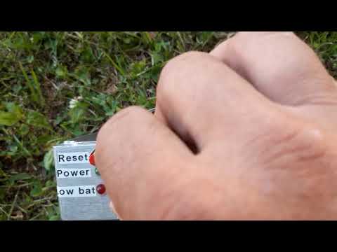
    I will try to attache two videos showing this sound.
    Delta Pulse 01 is with connected coil
    Delta Pulse 02 is with no coil


    I have changed the VT1, no noticeable change. The lines looks good.


    I have to tell you that I am very glad that you take your time to support me.
    Leave a comment:


  • kt315
    replied
    And R5 (680ohm) is getting hot very quickly. No coil is connected.

    --
    no AC signal on GATE of MOSFET. MOSFET is always in OPEN state and getting hot very quickly. yes, you have burnt power lines to the CMOS.

    Leave a comment:


  • kt315
    replied
    +E hightlighted by BLUE color and you can check the line in every points.
    Attached Files

    Leave a comment:


  • kt315
    replied
    sorry, you can not measure impulse signals like DC signal. all (those) test points for o-scope check.

    that I have no Vcc to pin8 on 555.
    ---
    check +E on all ICs and seek up where you got burnt track.

    Leave a comment:


  • Loola
    replied
    Kt315
    Before I desolder VT9, let me tell you that I have no Vcc to pin8 on 555.


    I have measured the test pins, maybe that can share some light over this.
    Battery 13.3V
    -12V to T1 11.6V
    -12V to T2 1.53V
    -12V to T3 12.55V
    -12V to T4 1.4V
    -12V to T5 1.4V
    -12V to T6 11.48V
    -12V to T7 2.3V


    And R5 (680ohm) is getting hot very quickly. No coil is connected.

    Leave a comment:


  • kt315
    replied
    you see this method is just classic generator. NOTHING SPECIAL.

    ali has much generators on NE555 and every can be used for testing of 555.

    buy with LEDs and you will see your 555 is good or not, looking on the LEDs. those prices are lowest -!
    Attached Files

    Leave a comment:


  • kt315
    replied
    in this video i show how to check sound with all components. https://www.youtube.com/watch?v=QYlDjdhYp3E
    YOU HAVE VERY ACCURATELY TO DESOLDER VT9. but i am feeling you will tear the metallization.
    also people bens pins of components on bottom side that i NEVER suggested, but they do that again and again (why? i do not know the answer- !).
    desoldering of those pins sure kills the board.

    Leave a comment:


  • kt315
    replied
    Desoldering
    ---
    you begin to kill the board. i got those boards in repair and they are looking as FULL SH-T, metallization killed in every holes where people desoldered.
    you must learn to solder before, this is the Main Rule. the metallization gives the contact/conductivity between from one board side to another one.
    if you kill it the contact is lost and you get very big problems.

    Leave a comment:


  • kt315
    replied
    in especial done thread i told about HOW to check NE555. buy https://www.banggood.com/it/DIY-Digi...r_warehouse=CN

    and use.

    Leave a comment:


  • Loola
    replied
    Kt315
    I followed your example with the 555 and there was no sound. Desoldering and measure it, different values
    compared to a new one. Put a new one in, but still silence.


    Any advice on what next to check?

    Leave a comment:


  • kt315
    replied
    i suggested to people to solder just sound part at first. then check. it is simple way to check/get sound quickly in my opinion.
    no o-scope. no tester. simplest way, https://www.youtube.com/watch?v=ODtvLeWdre0

    Leave a comment:


  • Loola
    replied
    I have to correct myself, R1 is alright.
    Now I have changed VD7 and fixed the melted copper lane.
    And now the green and red LED came alive, but that maybe all there is.
    I have tested with two different coils but no reaction with metal beside the coils, just silence.


    Any further suggestions?
    I have a oscilloscope.


    And Kt315, Yes, I use color code, but this time Murphy was my assistent....

    Leave a comment:


  • kt315
    replied
    good fast fixing. recheck R1 (620k) on 1MOhm range of your tester.

    Leave a comment:


  • Qiaozhi
    replied
    Originally posted by Loola View Post
    I have just finished some measurements, and so far I have find that VD7, as you suggested
    is gone. Also R1 is gone and the copper lane between VD7 and TP E+.
    The problem with the so-called "protection" diode, is that you also need to have a fuse in series with the supply line, otherwise there is no protection. All that happens is that the diode let's out the magic smoke, and then other components get destroyed as well, along with some of the tracking. If you're lucky (fingers crossed), the burnt out track has acted as the fuse.

    Leave a comment:


  • Loola
    replied
    Impressively fast reply, thank you KT315.


    I have just finished some measurements, and so far I have find that VD7, as you suggested
    is gone. Also R1 is gone and the copper lane between VD7 and TP E+.


    I am on my way to change these parts now and will update the outcome.

    Leave a comment:

Working...
X