Announcement

Collapse
No announcement yet.

Advanced PI coils

Collapse
X
 
  • Filter
  • Time
  • Show
Clear All
new posts

  • Aziz
    replied
    Flat Spiral Coil Online Calculators

    Interesting online inductance calculators for you:
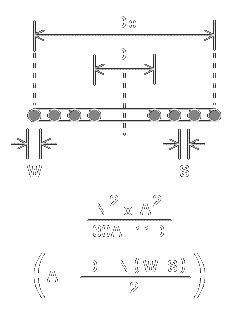


    I need 35 loop turns for ~300 µH (Di=127 mm, N=35, w=1 mm, s=0.814 mm, -> Do=254 mm = 10"). My coil software is proposing N=34.7 for a 10 turn spiral approximation (just to speed it up, seems to work ok ).

    Aziz

    Leave a comment:


  • Aziz
    replied
    Originally posted by Aziz View Post
    ...
    Notice, the coil comparision between the Dual Field and the mono coil was a direct coil comparison and the SNR wasn't taken into account on the Dual Field coil (just normalized to 300 µH). As we know, small coils with small coil flux area do induce less EMI noise, the Dual Field coil should be a little bit quiet. On the other hand, we have more copper and more turns count, which could screw the SNR. This is a great question, whether the SNR gets screwed or not. I have to make a SNR normalized coil comparision to figure it out.
    ..
    Ok, the answer to the above is: only 1% less EMI noise induction improvement.
    Ignore this little improvement (not significant). It has the same EMI noise induction performance compared to a mono coil.

    All the additional copper wire is screwing up our SNR. Can we expect the same result with spiral coils? Or gets the SNR even worse? A lot of interesting questions and my brain is smoking...

    Aziz

    Leave a comment:


  • WM6
    replied
    Originally posted by mikebg View Post

    How the balance circuit with MONOCOIL will suppress the GND signal?
    Very easy with 8 shape mono coil, you even do not need electronic support.

    Leave a comment:


  • mikebg
    replied
    Originally posted by deemon View Post
    Believe me or not , Aziz , but the "world best coil technology" is just the simple monocoil with additional balance circuit ...
    Deemon, how should be controlled the balance circuit - automatic or manually?
    How the balance circuit with MONOCOIL will suppress the GND signal?

    Leave a comment:


  • Aziz
    replied
    Originally posted by Orbit View Post
    H2O+H20=H2O????
    I prefer H20 + C2H5-OH, called beer.... *LOL*

    Leave a comment:


  • Aziz
    replied
    Originally posted by Ferric Toes View Post
    ...
    Would not the Dual Field coil have a similar performance? That's what your calculations for the DF would suggest.
    ...
    Hi Eric,

    the Dual-Field coil can be considered as a first approximation of a spiral mono PI coil (provided that, both coil parts have the same number of turns count).

    A Tri-Field coil a second best approximation (0.5, 0.75, 1.0 diameter unit).
    Continue with the splitting and it becomes the spiral coil at the end.

    Notice, the coil comparision between the Dual Field and the mono coil was a direct coil comparison and the SNR wasn't taken into account on the Dual Field coil (just normalized to 300 µH). As we know, small coils with small coil flux area do induce less EMI noise, the Dual Field coil should be a little bit quiet. On the other hand, we have more copper and more turns count, which could screw the SNR. This is a great question, whether the SNR gets screwed or not. I have to make a SNR normalized coil comparision to figure it out.

    Originally posted by Ferric Toes View Post
    I'm not a betting man, but at a guess I would say that it is the same as a normal mono of mean diameter 0.75.
    One would assume this but the answer is no! Mean diameter of 0.75 won't work equal.

    I see, I have a great new job to find all the interesting answers ...


    Cheers,
    Aziz

    Leave a comment:


  • Orbit
    replied
    H2O+H20=H2O???? V=S:T ==> S=VxT ==> T=S:V S !!

    Leave a comment:


  • Orbit
    replied
    Give something concrete without can be or may not be !!!

    Leave a comment:


  • Ferric Toes
    replied
    Originally posted by Aziz View Post
    Ok, let's continue with the spiral mono PI coil now... (requiring more processing time however)
    I'll begin the spiral at 0.5 times diameter and end at 1.0 times diameter units.
    (Before you quickly run into the patent office, wait, wait!, it's prior art... *LOL* )

    How is that spiral coil comparing to the equivalent mono coil regards to SNR?

    (Anyone want to bet? My betting office has been opened right now. )
    Aziz
    I'm not a betting man, but at a guess I would say that it is the same as a normal mono of mean diameter 0.75. Its detection range can't be as good, so for an object at the limit of detection for 1DU the SNR is all noise and no signal for the spiral coil. You need to specify what sort of noise, what type of object, and position of object on the coil axis. Best to use a spherical object at least 1/10th of mean coil diameter, so that the 6th power law applies for distances greater than the mean radius, and no orientation problems. All coils I have seen, shielded or NC have a NSR, not SNR. The signal is lifted out of the noise by synchronous processing and averaging and only then do we have a SNR.

    Would not the Dual Field coil have a similar performance? That's what your calculations for the DF would suggest.

    Eric.

    Leave a comment:


  • Aziz
    replied
    The Spiral Mono PI Coil?

    Ok, let's continue with the spiral mono PI coil now... (requiring more processing time however)
    I'll begin the spiral at 0.5 times diameter and end at 1.0 times diameter units.
    (Before you quickly run into the patent office, wait, wait!, it's prior art... *LOL* )

    How is that spiral coil comparing to the equivalent mono coil regards to SNR?

    (Anyone want to bet? My betting office has been opened right now. )
    Aziz

    Leave a comment:


  • Aziz
    replied
    Originally posted by deemon View Post
    Believe me or not , Aziz , but the "world best coil technology" is just the simple monocoil with additional balance circuit ...
    No! Don't give up quickly mate.

    There must be left over at least one big coil invention to the smartest guy (or girl). I'm just waiting for the guy, who is giving or kicking off the crucial coil idea. Comeon!, don't be evil. Let the cat out of the bag now.


    Aziz

    Leave a comment:


  • deemon
    replied
    Originally posted by Aziz View Post
    Hi all,
    Ok, what's left over? Any forgotton coil types? Wishes?
    Let's invent together the "World's Best Coil Technology" (WBCT) now.
    Believe me or not , Aziz , but the "world best coil technology" is just the simple monocoil with additional balance circuit ...

    Leave a comment:


  • Aziz
    replied
    Hi all,

    I have bad news:
    The simple assumption for the approximation of the target orientation doesn't work. It's obviously quite non-trivial and requires either much much more processing power by trying many many different random orientations (the Monte-Carlo Method) or another approximation idea.
    Exact solution would be:
    Solving very very complex integral equations.
    (Who is going to dare it? Nooooo!, don't look at me! I'm not that smart. )

    But the code for aligning the target orientation (aligning the target coil axis into a given vector-axis) works perfect.
    (That wasn't trivial too. But a brilliant idea made it easy.)

    The Monte-Carlo Method would blow up the processing time (although much easier to code). We should continue to use the fixed target orientation analysis until I get another brilliant idea or implement the Monte-Carlo Method.

    Ok, what's left over? Any forgotton coil types? Wishes?
    Let's invent together the "World's Best Coil Technology" (WBCT) now.

    Cheers,
    Aziz

    Leave a comment:


  • mickstv
    replied
    Hi Eric, this is the diff amp circuit I've been using in my latest experiments. The resistor values are for reference only.

    Leave a comment:


  • Ferric Toes
    replied
    Originally posted by bbsailor View Post
    Eric,

    it seems that you derive additional sensitivity by operating at 13Kpps and then integrating those RX samples to improve the signal to noise ratio. The PI MD design is then extracting a weak target signal burried in noise by acting like a "Lock-in Amplifier". http://electron9.phys.utk.edu/optics...m10/tn1000.pdf

    With a 13Kpps pulse you would have a square wave of 1/13000 or 76.9 uS divided by 2 or about 38.5uS for a square wave. So if the waveform is flat topping then it must be at or near 5 Time Constants on the coil charge side. 80uH/30 ohms (27 ohm resistor plus coil resistance and MOSFET on- resistance) or about 2.6 us so the a pulse width of 7.8 uS provides about 85 percent max current and 13 uS provided 100 percent of max current. As you mention the S/N is good after integration because your High Frequency design makes up for the "Brute Force" method of putting a lot of current in the coil by now emphasizing the receive side of detecting small target signals by integrating many signals.

    Is there an optimum number of RX signals to integrate?

    At 13Kpps scanning using a 10 inch actual size coil a sweep width of 40 inches or approximately 1 meter per second puts a target under the coil for about one fourth of the time or 13000/4 or 3250 pulses being integrated.

    Are all size targets equally sensitive to sweep speed or does changing sweep speed effectively retune the lock-in amplifier filtering effect to favor different target sizes and TCs or affect some target sizes and TCs the least?

    One of last areas of PI coil design has been ignored so far. I believe that putting the first amplifier/buffer stage in the near the coil will allow faster pulses to be integrated by lowering the capacitance seen by the coil by active RX buffering at, in, or near the coil. When the damping resistor is a higher value it means that there is less capacitance to damp and thus the coil discharge curve is faster and thus can better stimulate smaller targets. A 320 uH coil that is center taped will have each coil be 1/4 the total inductance or 80uH. What value damping resistors do you have across each coil? I suspect the sum of the two is a higher value than a single damping resistor would be on a typical mono PI coil.

    Thanks

    bbsailor
    Hi bbs,

    It is a little different in that the TX pulse, when sampling at 7uS, is 21uS wide and looking at the voltage, or current, waveform, it has just about reached its max at shut off. It I drop the clock frequency so that the sampling delay is 10us, then the TX width is 30uS. Always 3X. So for a 20uS delay, TX would be 60uS. As I have it set up, with a delay of 7uS, then the period is 70uS i.e. 14.28 kps. A little up on yesterday due to driving the mosfet better and winning a uS.

    I have only 1ft of lead between coil and electronics so if I had a standard cable length, then things would be degraded. I just have three wires plaided as it is a differential system. For fast industrial systems the coil was wired to the electronics by no more than two or three inches of cable. OK as long as there is no relative movement and components with plated steel wires kept at a distance. 1N4148s for instance. Also electrolytic caps with ali cans.

    Damping is a 1K fixed resistor in series with 1K cermet preset. One across each half of the winding. One opamp input is inverting so that presents a parallel resistor. Each preset has to be adjusted separately with the one on the non-inverting input seeming to be more critical. As I say, the preamp as it is, is not ideal and a better one will be built for this coil.

    Response is very fast and I will probably increase the integrator TC a bit to smooth out the noise still further. I also have a switchable 1st order/2nd order LP filter after the integrator which sharpens up the overall response nicely for accurate pinpointing. With everything running and audio on phones, the current consumption is 125mA at 12V, whatever the TX pulsewidth and pulse rate.

    Eric.

    Leave a comment:

Working...
X