Announcement

Collapse
No announcement yet.

spiral pi coil

Collapse
X
 
  • Filter
  • Time
  • Show
Clear All
new posts

  • godigit1
    replied
    Originally posted by green View Post
    Isnt the coil SRF the coil SRF no matter what way you measure it?

    The measurement method can effect resonant decay. Decay resonance is circuit resonance maybe not coil resonance. Thinking method that gives the highest resonance is closer to coil SRF.

    Hi godigit. I get less than 10pf with my spiral coils, no shield no lead wire. Wondering why your capacitance is higher. Do your coils have leads? Maybe using different measuring methods?

    Hi Green,
    All the test coils Ive made have leads.
    I think we are calcing capacitance the same way. Ive double checked the calculator Im using to specs from some of your coils. But maybe my SRF is wrong?
    This is the calculator Ive been using.
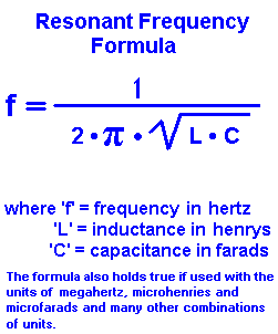

    Im wondering if the less capacitance of your coils is due to larger wire diameter? I have a oval spiral I did some time back with 26 awg I dont think I brought it in my on the road box. Ill have to check. I never tested it for Srf or capacitance. Curious Now!
    Thanks,

    Leave a comment:


  • Altra
    replied
    Originally posted by godigit1 View Post

    Does anyone know of a chart that correlates Q to usable frequency?
    I thought I had found one but its lost to me at the moment.
    On a normal PI, pulsing frequency or "PPS" has nothing to do with the Q or SRF. The srf and Q are about how fast a coil can release the stored energy (current). The higher the SRF the narrower the flyback period the sooner you can sample.

    So you are not going to find a pulsing frequency for a certain Q coil

    Leave a comment:


  • green
    replied
    Isnt the coil SRF the coil SRF no matter what way you measure it?

    The measurement method can effect resonant decay. Decay resonance is circuit resonance maybe not coil resonance. Thinking method that gives the highest resonance is closer to coil SRF.

    Hi godigit. I get less than 10pf with my spiral coils, no shield no lead wire. Wondering why your capacitance is higher. Do your coils have leads? Maybe using different measuring methods?

    Leave a comment:


  • godigit1
    replied
    Originally posted by Altra View Post
    Thank you guys for this?
    I redo my calculations.

    Does anyone know of a chart that correlates Q to usable frequency?
    I thought I had found one but its lost to me at the moment.

    Leave a comment:


  • godigit1
    replied
    I finished my 5 test coils and will start target testing soon.
    But I did find something unexpected on my last two coils .
    The first three coils all the same wire length showed a slight reduction in capacitance as the spacing was increased as well as a reduction in inductance.
    On my coils that i tested at the same inductance Im seeing a hump in the capacitance that it increases at one wire space and drops at two wire space.

    Coil 3 298uh 2 wire spacing 28 wraps
    5.9 ohms
    1.667Mhz
    30.588pf
    Q530

    Coil 4 1 wire space. 27 wraps
    306uh
    5.5ohms
    38.255pf
    Q513

    Coil5 No spacing 26 wraps
    308uh
    5.2 ohms
    1.563mhz
    33.664Pf
    Q581.

    So capacitance has come full circle from my first coil.
    Coil 1 no spaceing was
    390 Uh
    5.9 ohms
    1.389 mhz
    33.664 pf
    Q576
    So its strange that both the no spaceing coils have the same capacitance yet there is a two wrap and 80 Uh diffrerance inductance.
    So far my conclusion is that there is a increase in capacitance with spacing in coils with the same inductance.
    I think this is beacuse of the extra wrap needed to make the one wire spacing coil the same inductance.
    On the two space coil there is the reduction in capacitance but at the cost of inductance. there are two more wraps added to get the same inductance.
    At two wire spacing I think there is no drop in capacitance due to loss of proximity effect and that it has no real benefit to performance maybe a deficit due to the inductance loss.

    Anymay thank you guys for all the training Ill try to get some target test data going soon. I can kinda ascertain what the coils are going to do but maybe Ill be suprised.
    Last edited by godigit1; 09-07-2019, 06:05 PM. Reason: word error

    Leave a comment:


  • godigit1
    replied
    Hi All,
    Isnt the coil SRF the coil SRF no matter what way you measure it?
    Other than free air measurements where you may get a little higher Srf shouldnt the Srf be the same ?
    Im still trying to learn and the test procedures can be confusing from one method to the other.
    Seems that Carls method of just not adding a damping resistor to a working Pi would be the most true to real world SRf at actual Pi operating frequency.

    Elliot,
    Thanks for tha killer job on your coil construction guide.
    If I input the data for your coil into the calculator Ive been using I get a Q of 765.4612.
    Are my perimeters correct?
    300uh
    1.366 ohm
    555khx SRF
    Of the coils Ive been testing the only other one ive tested with a q in that range is a 8 inch 3dSS.
    All of my spiral coils with 30 awg do not have that high a Q even though capacitance is less than half on some of them.
    Im wondering when you can take first sample with your design. And did you by chance test before and after shielding?.

    Thanks,

    Leave a comment:


  • Altra
    replied
    Originally posted by green View Post
    I've been using (Q=pi*cycles to decay to 37% of start amplitude). Tried your formula(Q=5*cycles to decay to 50% of start amplitude)with my spice simulation. Looks like multiplier should be closer to 4.3*cycles to 50% of start amplitude. I'm rounding .368 to .37. Are you rounding or am I doing something wrong? Don't have a signal generator to try your method to compare with mine. Wondering if you could try my method to compare with yours. Clip scope probe to ground lead making a loop. Lay loop on test coil and move test coil near a operating PI coil to excite resonance. Measure decay frequency with scope.
    On this page he uses 4.53 as the multiplier.


    @Elliot, nice article and analysis

    Leave a comment:


  • green
    replied
    Originally posted by Elliot View Post
    I wrote this guide for how to build a search coil for the Mirage PI, and added toward the end, the approach I use to measure the SRF, Q and Parasitic capacitance of a coil (including the coil lead to the pcb case). I thought some others may find it useful.
    I've been using (Q=pi*cycles to decay to 37% of start amplitude). Tried your formula(Q=5*cycles to decay to 50% of start amplitude)with my spice simulation. Looks like multiplier should be closer to 4.3*cycles to 50% of start amplitude. I'm rounding .368 to .37. Are you rounding or am I doing something wrong? Don't have a signal generator to try your method to compare with mine. Wondering if you could try my method to compare with yours. Clip scope probe to ground lead making a loop. Lay loop on test coil and move test coil near a operating PI coil to excite resonance. Measure decay frequency with scope.

    Leave a comment:


  • kt315
    replied
    There are a number of ways to shield
    coils, including foil, wire wrap, metallic
    tape, and conductive spray coatings.
    A simple method is to wrap the coil
    with aluminum duct tape, the kind easily
    found at the local home
    improvement center. This is the tape
    that is true aluminum, not the silvery
    metallic-looking fabric duct tape. Standard
    duct tape is slightly conductive,
    but not enough for shielding.

    i took this cutting from Carl text. you see the material is not foil, but aluminum duct tape.
    also take attention on word slightly conductive. so really it is just a micro thin aluminum film on dielectric base practically NOT conductive.
    while we see fat copper tape in this PDF the man used.

    However, Eric recommended some conductive fabric tape
    ---
    here in Europe, on continent, we use GRAPHIT 33 https://www.youtube.com/watch?v=GitaTiM1A3A
    Belgian made.

    The world-famous graphite mineral, due to its unique properties, including high electrical conductivity, is used in various industries and, accordingly, a number of necessary goods, let us consider one of the types of which, using the Belgian aerosol product Graphit 33 as an example, consists of highly purified colloidal graphite .. .

    Click image for larger version

Name:	graphit33.jpg
Views:	2
Size:	96.9 KB
ID:	354849


    Leave a comment:


  • Qiaozhi
    replied
    Originally posted by kt315 View Post
    foil shield is killing all sensitivity. i see nothing of exellent. just he splitted the coil from foil thats right and did not fill by epoxy also right.
    I have used foil tape for shielding without any huge loss in sensitivity. However, Eric recommended some conductive fabric tape which is better -> https://www.ebay.co.uk/itm/UK-20M-Co...72.m2749.l2649

    Leave a comment:


  • kt315
    replied
    Originally posted by Qiaozhi View Post
    Thanks for the info. Excellent work!

    foil shield is killing all sensitivity. i see nothing of excellent. just he splitted the coil from foil thats right and did not fill by epoxy also right.

    Leave a comment:


  • Qiaozhi
    replied
    Originally posted by Elliot View Post
    I wrote this guide for how to build a search coil for the Mirage PI, and added toward the end, the approach I use to measure the SRF, Q and Parasitic capacitance of a coil (including the coil lead to the pcb case). I thought some others may find it useful.
    Thanks for the info. Excellent work!

    Leave a comment:


  • 6666
    replied
    Originally posted by Elliot View Post
    Just wondering what method others use to measure the SRF of coils.


    I use a simple LC oscillator and freq counter ,tried a couple of ccts, happy with results, but still got a couple more ccts to try to see if they get higher frequency from coils (less parts)

    Leave a comment:


  • Elliot
    replied
    Method of Measuring the SRF and Q of a coil at the operating TX frequency

    I wrote this guide for how to build a search coil for the Mirage PI, and added toward the end, the approach I use to measure the SRF, Q and Parasitic capacitance of a coil (including the coil lead to the pcb case). I thought some others may find it useful.
    Attached Files

    Leave a comment:


  • Elliot
    replied
    Originally posted by green View Post
    Wondering if the reason the professional coil is better is measurable. Have you compared diameter, inductance, resistance and SRF with your coils? Maybe some other measurements? Another possibility, professional coil has less noise for some reason? Are you testing with a short or long TC target? Test I did awhile back with some of the coils you sent me. Your coil is better at close distances than my spiral coil, smaller diameter is some of it. Still looks like your winding might be a little better for some reason. Zapped my test circuit with integrator awhile back or I would try testing again to see if I missed something.
    Just wondering what method others use to measure the SRF of coils.

    Leave a comment:

Working...
X