Announcement

Collapse
No announcement yet.

Announcement

Collapse
No announcement yet.

Mono Coil problem

Collapse
X
 
  • Filter
  • Time
  • Show
Clear All
new posts

  • Mono Coil problem

    Hello everyone.
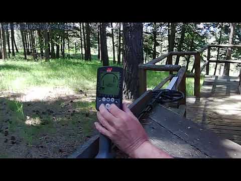
    I've built an 8-inch mono coil for my TDI SL using Litz wire salvaged from an original Minelab coil. I painted the housing with high-quality graphite paint, and so far, everything looks perfect. The connecting cable is the same original Minelab coaxial cable. The coil detects small gold nuggets very well. The problem is that it detects a hot rock right at the junction of the coil wire and the coaxial cable, precisely under the cable gland. Elsewhere on the coil, the hot rock doesn't register any signal, only at the connection I mentioned earlier. I'd like to know if anyone has encountered this problem before, as I don't know how to solve it. If I increase the delay to 17µs, the problem disappears, but that prevents the detection of gold nuggets. Thanks in advance.

  • #2
    Hi Eduardo,
    I don't know what is your exact problem, but the detector don't knows that only the coil have to react on the near targets. The coil and the cable are common "sense part" of the detector. Some years ago, I noticed the similar problem in my attempt to made very speed PI detector. A near hand (not only metal target) to the screened cable made reaction. Serious reduction of this side effect was made only when the final TX stage and the first RX stage was mounted on the small board inside the coil's part. Try to made the first RX stage (or both - Final TX stage and the first RX stage) on the small PCB. Some serious manufacturers uses small ferrite boxes as screen for this PCB inside the search unit.

    Comment


    • #3
      Your problem is a too-large solder joint. The hot rock creates a magnetic field deflection that induces an altered eddy current in the solder joint and makes it look like a dynamic target. If you have ITMD3, see 28.5. There are 3 approaches to fixing this:
      1. Always minimize the size of the solder joint.
      2. Minelab has a patent on encasing the solder joints in ferrite, see WIPO 2011/116414.
      3. On some of his PI coils, Eric Foster would ad a ~25mm "tower" to the gland and use that to place the solder joints away from the ground.
      Click image for larger version  Name:	image.png Views:	0 Size:	917.4 KB ID:	445241

      I also demonstrated this problem in a youtube video as caused by a carbon fiber lower rod:


      Edit: For me, the video is not jumping to the right time. Skip ahead to 8:50.

      Comment


      • #4
        Thanks Carl and Detectorist1 for the help.
        Carl, I have all your books, including ITMD3. I've attached a link to a short video I made so you can see exactly the problem I'm having. I've made the ground connection with a longer wire; in the video, it's the green wire.​
        https://www.youtube.com/shorts/8dLqJJD0Jxs

        Comment


        • #5
          In my opinion solder joints looks a little big and the space between the litz wire on the left (paralel wire) will act like a small coil. It needs to be a little twisted.

          Comment


          • #6
            My frequent and over-the-top jokes on the forum have given many people the impression that I am always joking.
            There's a very good reason why I suggested to Aziz on another thread that he get this from the link and play around a bit.
            One could very well visually see what is happening at the solder joints.
            Although it is also easy to assume.
            The biggest problem is not the solder joints themselves, but their position, which is in line with the lower coil windings.
            Lifting and removing the solder joints from the plane in which the coil is located would greatly alleviate the problem.
            Link: https://www.aliexpress.com/item/1005...origin_prod%3A

            Comment

            Working...
            X