-
Well, you *could" use the VDI that is on this sight, and instead of driving the display, use the DAC to drive an analog meter..... The whites works by using a logarithmic opamp for each channel, and then subtracting the results with an opamp. Subtracting two logrithms from each other, is the equivalent of dividing one by the other. So the x and y channel values get their logarithms computed. This is done by a matched pair of transistors, where one transistor is in the feedback of the two opamps. The transistor has a logarithmic voltage response, and generates a log amplifier. -
I know this is an old posting, but back in the Compass Coin Magnum days of Good/Bad meter, and migrating into the X70 and X80 Challenger, they used the "X" as the reference signal, and compared the other signals to it, to get the triggers for the potted module. I wanted to post the X70 meter circuit, to go along with the X80 meter TID circuit, but was not able to do so. Posting for a computer that runs with an old telephone line, using AOL, has too many restrictions, in comparison to the smaller memory chips in the older computer that I was restricted to, in order to run the other software which I paid for. So I see here now you are finally catching the reasons. The older TR machines, were not like the "phase shift technology", but they used reference signal comparison to trigger the good/bad and TID meters. It is why I am searching for a TID meter to go into the Coin Magnum and replace the older Good/Bad meters in it, and stay with NO MOTION discrimination rather, then have to go along with the damn MOTION DISC of today... I have my reasons which I will not explain.
MelbetaLeave a comment:
-
Hello friends
I hope everybody has a great time!
Not many days ago I have found an interesting little schematic, it's a VDI VCO.
Here is the VDI schematic, it has some errors but the pcb lay file is ok !
!
best regards!Leave a comment:
-
I looked at the patent, and that is how George Payne set up the Compass Electronics Coin Scanner and Coin Scanner Pro TID detectors.
MelbetaLeave a comment:
-
Originally posted by Carl-NC View Post
Thanks, Carl. That reminds me I should probably use that instead of the Goldbug style VCO I was planning on, but I have them both working with a multiplier output feeding them (on my laptop, anyway).
I know the OPs original intent was to gather ideas for a visual target ID. I would like to suggest instead, use VCO target ID, and reserve the meter for a depth indicator - (future endeavor maybe).
Anyway, after getting over the -missing- positive power supply, I think the RC4200 architecture is pretty slick. You set your own scale factor instead of having to settle for 1:10 as is common with most other multiplier ICs.Leave a comment:
-
Could you please post the schematic you are working on without it being encapsulated in a RAR file?Originally posted by Nandor View Post
RARs are not opening for me today for some reason.Leave a comment:
-
There is always the possibility that some of those NJM4200 on Ebay are the real thing and they are priced right for experimentation.
Everybody should take a look at the MAT02 datasheet, fig. 3. The '4200 is no longer so mysterious because what looks like transconductance amplifiers on the '4200 datasheet are now hugely simplified. LTspice and I could analyse the fig. 3 circuit over a couple beers and a bowl of Weedies.
So the RC4200 multiplier-divider isn't going to be so scary to work with but I would still like to know, where is the positive power supply?
time for another spam folder check ?Leave a comment:
-
A super-simple VCO is a 555 timer where pin 5 is used as the voltage control.Leave a comment:
-
Hmmm If just using the multiplier for vco control, I shouldn't really have to worry about calibration, either use the Toltec scheme, or else tap off x and y signals, sum them together, then divide y by the sum x+y, that way the result should always be one or less than one to keep from pegging the output. Maybe I won't breadboard, but instead tweak it in place after building the darn thing. Nothing critical, it's a noise maker, eh?Leave a comment:
-
It struck me a while back that what I would be needed for my project is Target ID VCO tone. SO, then I pulled out LTspice and tried to work up something using the el-cheapo AD633 analog multiplier. The data sheet has an application for an analog divider, so I gave it a try. Unfortunately, AD633 does not have a dedicated divisor input, so the multiplier is connected inside an op-amp's FB loop to implement division, and that seems to complicate the issue. I'm having trouble taming the LTspice output which seems to want to peg to one or the other supply rails instead of being "analog".
So, RC4200, RM4200, or NJM4200, may be the way to go - but they are kind of hard to find unless you want to try a Chinese clone. I may grab some and plug them into a breadboard to see if I can find some confidence to go farther. The fact that '4200 does have a dedicated divisor input should simplify things. '4200 has current output and inputs which is a little different, but we have the Toltek schematics to follow for a ready made "cookbook" solution.Leave a comment:
-
Hello Sir,,,Originally posted by Nandor View Post
You're welcome! You are Star here Sir Nandor you deserved it. You're right, but making VLF to get first real working is quite a struggle, so if one wants to build VDI they must have a good working made device with good discrimination & GB. Your idea is what we all want! The video is pleased that's enough, well for me... Anyway I just make a PCB couple hours ago but still need to check. Thanks again Sir for keep us update. RegardsLeave a comment:
-
Hello
Thank you for the kind words. I wish that this project was made ten years earlier when TGSL and IDX was very popular. Mr Gurdal is the the one I have to thank for the schematic and lay file.
The best would be 2 separate filters for the VDI circuit so it could work in all metal mode also. I was thinking about it and also 3 tone mode with comparators.
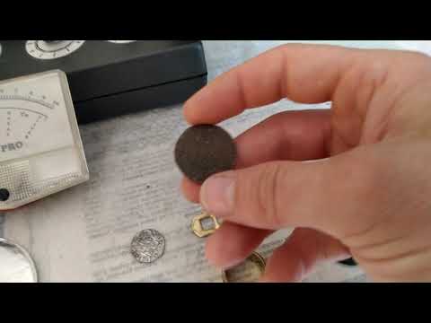
I have posted this in the IDX PRO topic
best regardsLeave a comment:
-
Ah..my bad. I've should've just sent you pm. It's not your fault, your pcb lay is very good, I mean you've gathered everything for us here, make it alive an give us scope measurement that was big job done, many many thanks for that Sir Nandor,, Umm since already proven this analog version is quite accurate, I try make my own PCB built-in instead extra board, that's when I found small error on the schematic. I will post my PCB later when I finished.Leave a comment:

Leave a comment: