Announcement

Collapse
No announcement yet.

Very simple Pi that works good

Collapse
X
 
  • Filter
  • Time
  • Show
Clear All
new posts

  • Very simple Pi that works good

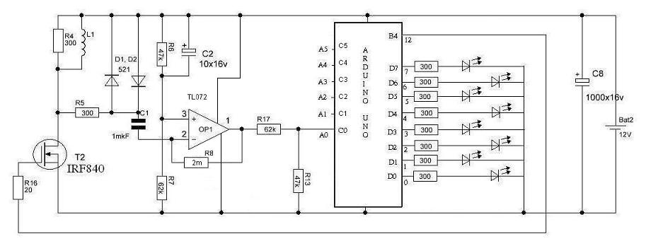
    Hello all I would like the experts to have a look at this simple PI schematic I have build this MD and it is working very well But what I would like to find out from the experts is Are there any Modifications I can make to make it more sensitive and detect deeper at the moment with a 15cm coil I get about 10 to 13cm detection depth on a R2 south African coin please have a look and let me know
    Thank you all
    I added the Schematic and the home build detector of mine


    Okay sorry cant find my homemade pics now will upload as soon as I have Please look at the schematic any changes would be helpful

  • #2
    General tech discussions on all types of metal detectors: VLF, 2-box, BFO, off-resonance, PLL, etc. Questions, ideas, and anything else that moves you.

    http://www.geotech1.com/forums/showt...light=simplest

    Comment


    • #4
      Originally posted by JOHANERIC112 View Post
      Hello all I would like the experts to have a look at this simple PI schematic I have build this MD and it is working very well But what I would like to find out from the experts is Are there any Modifications I can make to make it more sensitive and detect deeper at the moment with a 15cm coil I get about 10 to 13cm detection depth on a R2 south African coin please have a look and let me know
      Thank you all
      I added the Schematic and the home build detector of mine


      Okay sorry cant find my homemade pics now will upload as soon as I have Please look at the schematic any changes would be helpful


      Not sure I Understand how it's working at all without Delaying the Sample.

      Comment


      • #5
        arduino uno used like a hammer in hands of the imbecile. if you mention arduino you have to mean:

        - arduino wireless transmitter module 2,4GHz IN A COIL inside, with TX part
        - two frequencies 5-6kHz and 12-15kHz working together in RX part
        - LCD matrix 128x64 pixels or color TFT touchscreen with VDI and Godograph with receiver module

        all on what arduino genius users are able - to take something simplest connecting LEDs to it ((( BAD

        Comment


        • #6
          Originally posted by homefire View Post
          Not sure I Understand how it's working at all without Delaying the Sample.
          The sample is delayed by R13/C8.

          Originally posted by kt315 View Post
          arduino uno used like a hammer in hands of the imbecile. if you mention arduino you have to mean:

          - arduino wireless transmitter module 2,4GHz IN A COIL inside, with TX part
          - two frequencies 5-6kHz and 12-15kHz working together in RX part
          - LCD matrix 128x64 pixels or color TFT touchscreen with VDI and Godograph with receiver module

          all on what arduino genius users are able - to take something simplest connecting LEDs to it ((( BAD
          Better use the processing power for useful things like ground cancellation, auto-adjustment and discrimination.

          Arduino can be replaced by an ATTiny84 MCU chip and the program still works. This gives a minimalistic but very flexible system.

          Comment


          • #7
            Arduino can be replaced by an ATTiny84 MCU chip and the program still works. This gives a minimalistic but very flexible system.

            STALKER and SKIF were realised on ATTINY15L. DIP-8 case! it is extremely pop up popular PI deeeper in UA and RU.
            Tracker, Koschej 4I 5I, Clone were realised on AT90S2313. extremaly popular in RU and UA! SIMPLEST PRIMITIVE!

            why nobody is able to take this schematics and to remake its in arduino -???

            Comment


            • #8
              I have a 20K pot in R13 but even when turning there is no change in sound or anything I think its useless there dont know why it should be there does any one know why R13 is placed there for what reason

              Comment


              • #9

                Comment


                • #10
                  Looks like that coil is under damped, therefor the detector may respond to the ringing of the coil rather than pulse sampling (could this be a new type of PI)?

                  Comment


                  • #11
                    Actually it is more likely overdamped, but it may only negligibly hurt the depth. The less obvious part is that it uses a single balanced modulator instead of a switch, and it may prove useful even in a more sophisticated gear. I found a short discussion about this device here: http://vrtp.ru/index.php?showtopic=21301

                    This kind of switch may withstand quite high flyback voltages - depending on the diode speed and reverse polarity strength.

                    I played with a simple series diode limiter before, in a way the very same thing as presented here, only constantli positive biassed. I also abandoned the idea because of the somewhat conflicting need for high impedance and simultaneously high-ish current, see http://www.geotech1.com/forums/showt...934#post145934.
                    It may be sorted out with current sources instead of resistors, but ultimately the dynamic resistance of a diode is set by its thermal voltage, and it is ~25mV/Ibias. With bias currents at 1mA the dynamic resistance is ~25ohm, and diode noise is below 1nV/sqrt(Hz). So there is a potential.

                    I'll pour this device into Spice and see what else may be found there.

                    Comment


                    • #12
                      Originally posted by Davor View Post
                      Actually it is more likely overdamped, ...
                      Davor, I need here some more explanation.

                      According my understanding for ordinary mono PI coil:

                      low damping R (say ~<1111R) mean over-damping

                      high damping R (say ~>1111R) mean under-damping

                      Here we have 3300R.

                      How we can explain that using such R coil become over-damped?

                      Comment


                      • #13
                        Although the driving transistor is m̶a̶r̶k̶e̶d̶ ̶5̶1̶0̶ not marked, I may only guess what transistor that is, the BJTs in general have quite less capacitance than MOSFETs, hence the damping requirements are less, not more. Even with MOSFETs a normal coil would critically damp at over 400 ohm, so I conclude that 330 ohm is overdamping it. Sure, if a coil is of less inductance (unlikely) or badly made, 330 would be too high, but that's unlikely.
                        Last edited by Davor; 11-16-2015, 03:20 PM. Reason: confusing schematic

                        Comment


                        • #14
                          But it is 3300 (3k3 or orange, orange, red - color mark) not 330?
                          On my display third color is red not brown.
                          Is this color mark on your display more brown than red?
                          Colors looks like this on my display (could be different on other display):

                          Comment


                          • #15
                            Directly compared with the colors of the other resistors and their values
                            plus with there vertically from up to down color-rings coding it's 330.

                            But of course the colors on that schematic are pretty bad:
                            orange looks like pink or rosee there and brown as dark red.
                            Attached Files

                            Comment

                            Working...
                            X