Announcement

Collapse
No announcement yet.

Pulse Star II (first analog version)

Collapse
X
 
  • Filter
  • Time
  • Show
Clear All
new posts

  • Mehr076
    replied
    Originally posted by Orbit View Post
    Here is the correct schematic of the Pulse Star 2 motherboard​!
    Hello, this schematic is not correct and has many errors.

    Leave a comment:


  • ivconic
    replied
    The good thing about the PS2 Pro is that those machines never break down.
    I had dozens of them on the service, but mostly they were very easy services.
    Potentiometers or coil connections mostly fail.
    But I have never seen any such detector have a main board failure.
    Sometimes, due to age, oxidation has occurred on the two-way pin arrays, and it is enough to just separate and reassemble the main board with the front and back.
    Big congratulations to the author!
    ​

    Leave a comment:


  • Mehr076
    replied
    Originally posted by N@SKO View Post
    I'm looking for PS2pro clear pcb pictures
    Pulse star ii pro
    Attached Files

    Leave a comment:


  • N@SKO
    replied
    I'm looking for PS2pro clear pcb pictures

    Leave a comment:


  • MDfanatic
    replied
    Copied from this link

    Original PS2 coils:
    25cm coil = 1.5 ohms, 0.611mH
    45cm coil = 1.9 ohms, 0.677mH
    1x1m coil = 2.7 ohms, 0.361mH (this I am not sure)
    2x2m coil = 2.5 ohms, ~1mH​

    Leave a comment:


  • crni1
    replied
    Greetings to all participants of this thread. I have a Pull star II built according to this scheme. I am interested in a 40cm probe. which wire is the best to wind, what is the diameter, and are there electronics, resistors, capacitors, etc. in these probes. Thank you.
    Attached Files

    Leave a comment:


  • kt315
    replied
    you can check yourself.
    Attached Files

    Leave a comment:


  • sbalio1
    replied
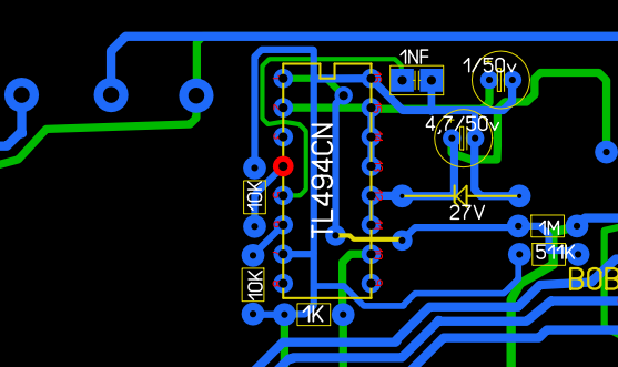
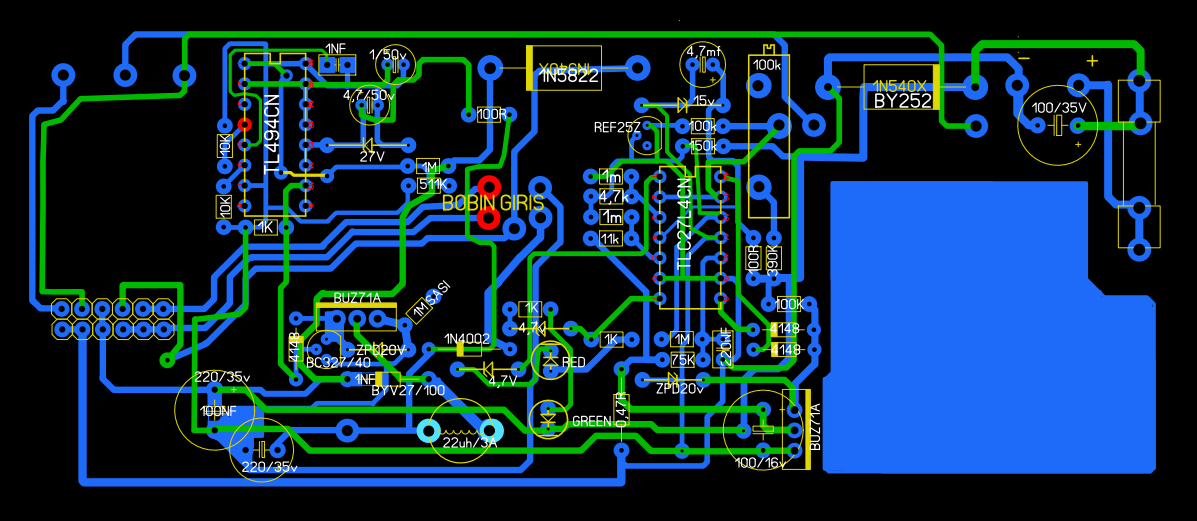
    hi to all the error i see is TL494 CERCUIT POINT LEG please cheeck it

    Leave a comment:


  • sbalio1
    replied
    hi all freinds i want to ask abaout this pcb i think it have error please if ennyone here get right pcb please help

    Leave a comment:


  • ivconic
    replied
    New store, branded. And from now on it will be the official store.
    https://vi.aliexpress.com/store/1104...bestmatch_sort

    Leave a comment:


  • ivconic
    replied
    Feel free to take my word for it, it will cost you less headache and much less work, and you get tested and trusted devices for installation:

    https://vi.aliexpress.com/item/10050...yAdapt=glo2vnm

    Leave a comment:


  • Mehr076
    replied
    Pulse starll , disc...

    Leave a comment:


  • roshik
    replied
    Originally posted by kt315 View Post
    Click image for larger version  Name:	Lorenz_box.jpg Views:	51 Size:	120.6 KB ID:	429314

    please if you have something new sharing on LORENZ in this topic pcb-lorens-5 - Geotech Forums (geotech1.com)​
    No unfortunately, I don't have more information about the Lorenz Pulse 5 circuit, but I think the op-amps used must be from the TL series.
    I think the user named mee has good information about this metal detector, and if he shares it, it will be a great help.​

    Leave a comment:


  • Mehr076
    replied

    Leave a comment:


  • kt315
    replied
    Click image for larger version

Name:	Lorenz_box.jpg
Views:	927
Size:	120.6 KB
ID:	429314
    Originally posted by roshik View Post
    Regarding the pl5 schematic, my information is also incomplete. I checked its schematic before and saw some small problems. Due to the unknown number of some ICs, I left it aside.
    I think that if the number of ics is identified, minor problems in its schematic circuits can be identified.​
    please if you have something new sharing on LORENZ in this topic pcb-lorens-5 - Geotech Forums (geotech1.com)​
    Last edited by kt315; 10-10-2024, 12:30 PM.

    Leave a comment:

Working...
X