Announcement

Collapse
No announcement yet.

Bounty Hunter Red Barren 7 schematic

Collapse
X
 
  • Filter
  • Time
  • Show
Clear All
new posts

  • #46
    Oh dear, I thought it was going ok but it wasn't, yes I had a steady tone for a while but there did seem to be a loose connection somewhere. I found that one of the large control panel pots (disc level pot) had turned inside so that one of the pins was touching the case. Strange because the pot was secured tight to the panel. Anyway I obviously twisted that out of the way & presumably that was the source of my initial fault where the battery pack shorted out & that permanent short had stopped during the disassembly of the unit.
    But all I get now is an intermittent on/off tone, sometimes it's constant on & off & other times it is off for approx 5 secs & then back to on/off again. Twiddling the knobs (setting it up with the manual) doesn't seem to work or alter the tone too much but presumably the tone should be constant or off depending on how well it is setup.
    So any ideas what makes it go on & off without me touching it?

    Comment


    • #47
      RED BARON SINGLE BOARD AND THREE BOARD CLARIFICATION

      HELLO TO ALL SPECIALLY MarksSupplies I SEE YOU HAVE SOME BATTERY WIRING PROBLEMS
      BECAUSE I WENT WITH THE SAME PROBLEM BUT THE SINGLE BOARD MODEL.I THINK I CAN HELP YOU.FIRST THE 840 VLF/TR MODEL DIAGRAM THAT PORKLURV TRIED TO EXPLAIN HE WAS 100 PERCENT CORRECT IT USES THE SAME SYSTEM POWER WIRING BUT LESS VOLTAGE HENCE ONLY TWO NINE VOLT BATTERIES INSTEAD OF TWO BATTERY PACKS OF 12 VOLT EACH.THAT'S HOW I HAD A GOOD IDEA WERE IN MY RED BARON THE FOUR POWER WIRES WENT TO,BUT I WAS NOT 100 PERCENT SURE.
      IN MY POST NUMBER THIRTY ABOVE THE FIFTH AND SIXTH PIC ARE THE SINGLE BOARD PICS THE ONE ON THE LEFT SOMEONE EVENTUALLY CAME FORWARD AND THERE WERE NICE TO TAKE A PICK OF THE ORIGINAL POWER WIRING AS THEY ARE.THE PIC ON THE RIGHT FROM THAT ONE IS MY BOARD OF HOW I THOUGHT GOING BY THE 840 MODEL WITCH TURN OUT TO BE THE RIGHT WAY.THIS HELPS YOU IN A WAY TO DETERMINE THAT IT IS 100 PERCENT THE POSITIVE AND NEGATIVE FROM EACH BATTERY PACK GO TO THE (RIGHT PLACE)COMMON GROUND AND THE OTHER TWO WIRES AGAIN POSITIVE AND NEGATIVE FROM THE WIRES LEFT GO TO THE OFF POSITION (CONNECTED THE RIGHT WAY ) IN THE SWITCH .NOW LOOKING AT YOUR PICS AND THE ONES I POSTED FROM PEOPLE THAT HAD THREE BOARDS BEFORE SOMEONE POSTED THE SINGLE BOARD.I'M GLAD I DID KEEP AND POSTED HERE.BECAUSE AFTER LOOKING AT YOURS AND THEIRS I CAN SEE AN OBVIOUS MISTAKE IN YOUR PART.SO IF YOU STILL HAVE IT AND TRYING TO FIGURE OUT HOW THE WIRES GO.LOOK AT MY PIC IN NUMBER THIRTY POST THE FORTH ONE ON THE RIGHT WITH THE TOOTH PIC POINTING AT THE BLACK WIRE.YOU NOTICE THERE ARE THREE BLACK WIRES TOGETHER AND TO THE LEFT THE RED WIRE SHOWN ON THE PIC ABOVE.WELL I HAD THE SINGLE BOARD SO I CAN'T PHYSICALLY TELL WHAT BOARD OUT OF THE THREE.BUT AFTER LOOKING AT YOURS IT'S THE SAME BOARD AS YOUR SECOND PIC IN POST NUMBER 35.AND YOU WILL NOTICE THAT YOU HAVE PUT THE NEGATIVE WHEN IT SHOULD BE THE POSITIVE FROM THE BATTERY PACK THAT THE NEGATIVE WENT TO THE OFF IN THE SWITCH GOING BY YOUR FIRST PIC POST NUMBER 35 YOU HAD THAT RIGHT.GOING ON THE NEGATIVE FROM THE OTHER PACK GOES RIGHT NEXT TO IT AND POSITIVE TO THE OFF SWITCH WITCH AGAIN YOU HAD THAT RIGHT GOING BY YOUR POST NUMBER 35 FIRST PIC.I HOPE IT'S NOT TOO LATE BECAUSE THAT WAS YOUR SOLUTION TO THE WIRING PROBLEM.ALL YOU HAVE TO DO AND THAT'S WHAT I DID AS SOON AS I SAW YOUR PROBLEM IS LOOK AT THE COLOR WIRES ON THE ORIGINAL THREE BOARD WIRING PIC NUMBER FOUR POST NUMBER 30 BY ME.FROM LEFT YOU HAVE (SOME ARE NOT VERY CLEAR FROM HIGHLIGHT) ORANGE-PURPLE-PURPLE-WHITE WITH PURPLE LINE-THEN (RED-BLACK)FROM EACH BATTERY TRAY THEN WHITE WITH RED LINE -RED-RED ETC.IN YOUR PHOTO YOU HAVE THE BLACK NEGATIVE.WHEN IT SHOULD BE POSITIVE.AND I NOTICED THAT YOU HAVE THE PLUS SIGN ABOVE IT ANYWAY.SO IF YOU STILL HAVE IT LEAVE THE WIRES ON THE OFF IN THE SWITCH LIKE YOU HAD IN YOUR FIRST PIC NUMBER 35 POST THEY SHOULD BE COMING FROM EACH OF THE BATTERY TRAYS (NOT ONE ONLY)THE COLOR SCHEME WAS RIGHT THERE IF FROM THE TWO TRAYS.THEN PUT THE POSITIVE FROM THE TWO REMINDING WIRES ON THE SAME TRACK WERE THE POSITIVE SIGN IS AND THE WIRE LEFT SHOULD BE BLACK TO THE FIRST CONTACT TO THE LEFT LOOKING AT YOUR PICK.THEN YOU SHOULD AT LEAST HAVE THE RIGHT POWER WIRING.DON'T FORGET WIRING POSITIVE AND NEGATIVE HAVE TO BE RIGHT AT THE POT SWITCH OFF POSITION.LOOKING AT YOUR FIRST PIC POST NUMBER 35 POSITIVE SHOULD BE HOW IT LOOKS ON PIC AT THE RIGHT AND NEGATIVE ON YOUR LEFT OFF POSITIONS AT THE BOTTOM (LOOKING AT YOUR PIC) HOPE THERE IS SOME CLARITY FROM ALL THIS BUT IT'S THE ONLY WAY TO EXPLAIN BY WORDS.IF THAT WAS YOUR ONLY PROBLEM AND YOU STILL HAVE IT.RED BARON LIVES AGAIN LIKE MINE

      Comment


      • #48
        Thanks Conan
        I've spent many hours on this problem and I have since found a number of faults that I have fixed but I still never got the dam thing working. In the end I asked a mate of mine to also have a look at it, he's also not been able to fix it it and he still has it so I can't quickly follow your information to see if I still have it wired incorrectly.
        I will post back here as soon as I have some more news.
        Thanks again Conan for your help, it's much appreciated.

        Comment


        • #49
          RED BARON 7

          THERE ARE SO MANY RED BARONS 3-5 AND 7 WITH THE SAME PROBLEM NOT WORKING AND IS MAINLY THE BATTERY PACKS.THEY ARE SO TIGHT AND SMALL MADE COMPARED TO THE SAME PACK BUT SLIGHTLY BIGGER BETTER MADE BUT THEY DON'T FIT IN THE CONTROL BOX HOLE WHERE THE BATTERY PACKS GO INTO.THE START OF THE PROBLEM IS NUMBER ONE THEY CRACK BREAK ON THE THING WALLS EDGES OR SPRINGS RUST OR BREAK.OWNERS THEN LOOK FOR THEM MAYBE FIND ONE BUT DOES NOT FIT AND GIVE UP ON IT.NEXT PERSON OR OWNER LOOKS AT IT AND THINKS I CAN PUT TWO NINE VOLT BATTERIES HENCE THE SNAP ON CLIPS WORK ON THEM.BUT DON'T REALIZE THAT BY LOWERING THE VOLTAGE YOU DO MORE HARM SINCE THE IC-LM358 GETS HOT VERY HOT AND UNTIL IT GIVES UP.ALSO THE SNAP ON CLIPS BREAK OR GET BROKEN BY THE WIRING INSIDE AND THAT'S THE PROBLEM I THINK YOU HAD.THEN THEY TRY TO FIGURE OUT WHERE THEY CONNECT AND THE PROBLEM KEEPS ACCUMULATING.BOUNTY HUNTER SHOULD HAVE KEPT LIKE THE 840 VLF/TR MODEL THE POWER SOURCE WITH TWO NINE VOLT BATTERIES.THAT'S WHY WHEN YOU GET TO THE RED BARON-10 THEY ONLY USE ONE 12 VOLT POWER PACK.AND THEY ARE ACTUALLY MORE POWERFUL DETECTING WISE.IT'S A SHAME THAT WITH LIFETIME WARRANTY THAT THEY HAD.THEY PUT SUCH A SYSTEM OF WEAK POWER PACKS AND LOUSY SNAP ON CLIPS.SPECIALLY THE COMPARTMENT SO TIGHT TO PUT SO MANY BATTERIES.THAT'S THE STORY OF THE RED BARON WEAK BATTERY SET UP
          ATTACHMENT PIC IS THE RED BARON AND RED BARON-10 WITH ONE PACK A LOT BETTER BUT STILL TIGHT COMPARTMENT TO PUT THE TRAY INTO AND THE TRAY SOLD ON eBay SOMEWHERE IN ENGLAND.
          Attached Files

          Comment


          • #50
            On 09-22-2008 homefire posted some pics on page 1 of this thread which photobucket has since removed. Did anyone save them and if so could they re-post them here? On the question of batteries overheating and how to wire them Carl is correct. A plus from one and minus from another go to common giving you a dual polarity power supply from the two remaining leads. As to one overheating I would look at the corresponding regulator circuit, likely at that age one of the 100 uF capacitors has shorted. Also if so most likely the transistor on the one in question has shorted due to excessive current flow. A very simple fix. I have noticed when BH finds a good method or circuit they like to re use it in other models. I notice on homefire's pdf of the RB7 he shows the coil circuit. I had drawn my Rustler dead bug and looking at the circuit I highly suspect BH used the identical coil for mine. I never bothered to redraw a better quality schematic as I could not determine the coil wiring, it has a circuit board inside buried under casting resin. Now I think it may well be the answer to finally finish my diagram except that some of it is not clear. There is one pot with no value, and I cannot tell if the two resistors are both 10 ohm or 100 ohm. I suspect if mine is the same the unmarked pot is in the meg-ohm range but not really sure. In my drawing I made an error on the arrow direction for the PNP transistor MPS6523 in the negative 6 volt supply. If I could get a complete schematic of the RB7 coil assembly I would take the time to improve my drawing. I am after much study quite positive the RB7 and Rustler coil assemblies are one and the same. The 90 and the 640 in the image names merely refer to rotation or shrinking of my original notebook scan. Anyway if you look at the supply regulator circuits I suspect they are similar to the model in question in this thread, maybe it would aid in repairing the RB7. On the MPSA13 I show it as a single device, the X2 darl refers to it really being a darlington transistor, hard to draw inside the little circle when your vision starts getting bad as at 58 mine has.
            Attached Files

            Comment


            • #51
              Forgot to mention but in the middle I state P4-gnd, refers to the LM392 on the right side being run single ended whereas the 358 in the middle is running dual polarity supply. As I stated had I been able to draw the coil portion properly I would have taken the time to make a better drawing, in the one shown it was my first try tracing the board and using whiteout corrections when I realized I had made errors in following the circuit. I post the drawing as it may be useful to someone working on a broken Rustler. Also the pot marked multi-turn is an interesting design using 3 large steel balls as a reduction drive which allows for slipping at the ends of rotation.

              Comment


              • #52
                Red Baron eating transistors

                Hello been reading quite abit of this thread during my saga of repairing my grandfather's old Red Baron (may he rest in peace). Been in the family since new and trying to get it working again to use. Worked great before it was put into storage but when taken out and powered up started smoking. To my knowledge no 9Vs were ever put into it but not sure. One transistor (MPS3638A) keeps burning even after replaced. It is circled in red on the pics. Not sure why. An orange capacitor nearby while in the circuit has a reading of 0 ohms (or really close). Will be taking it out to check though seems odd. Could it be shorted? How can I figure out the uf? Doesn't seem to be listed on it. Doesn't seem to be an electrolytic type. The power hook ups are original and the rest of the wiring looks correct (except the orange and orange/ white wires to the board which are circled in one pic). Could a bad coil cause this? It is the original and was never swapped. Anyone have a clue and can help? Power/ volume switch has been gone through and appear to work fine now. Thanks any help is greatly appreciated.

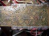
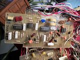
                The pic of the board is out of a 3 board model from the 1980s and is the one with the most wires attached (its NOT the Synchronous phase or the one mounted on the back of the meter).
                Don't know how to add pics yet so here's a link to Photobucket.


                and in case the above don't work here are the links
                http://i632.photobucket.com/albums/u...s/RedBaron.jpg
                http://i632.photobucket.com/albums/u.../RedBaron2.jpg

                ThanksI really appreciate any help.

                Comment


                • #53
                  Originally posted by NostalgicMeditations View Post
                  Don't know how to add pics yet so here's a link to Photobucket.
                  After you have made one post (and you've just done that) you have permission to add attachments.

                  Comment


                  • #54
                    Thanks- never guessed that. I would try to PM Conan since he has a lot of experience with the Red Barons but don't have the ability to do that yet either. Hopefully he'll notice the post or some else who can help me with this project. Would be neat to get it working again. It was hardley ever used but has been in the family since I can remember. Sad that Bounty Hunter didn't use higher quality parts. It took me hours to fix the loose contacts in the Volume switch to make it reliable (doesn't look pretty but it works all the time now). Mark Supplies if you do get the detector back I suggest the DPST contacts in your switch might be part of the problem with the intermittent operation (mine only worked sometimes according to my meter as well). I have a Nautlius (which has to go in for repairs suspect is coils and possibly more) but not much experience with any other detectors. The Red Baron hasn't been working for years.

                    Comment


                    • #55
                      Originally posted by NostalgicMeditations View Post
                      The Red Baron hasn't been working for years.
                      Is this any help?
                      Attached Files

                      Comment


                      • #56
                        Thanks Qiaozhi but I already downloaded those schematics and still can't figure it out. Actually the schematic for the coil hookup and the pics of Mark's RB-5 show 2 different hookups for the orange and orange/white wires going to the board. Mine is a RB-7. Tried both ways and no difference. Transistor still burns (one time it burned up so bad the terminal conections inside could be seen). So far a few of the Caps on various boards seem to be shorted? At least the ohm meter shows a connections to be shorting (haven't taken them out of the circuit to check the caps yet though. I think they are tantulum caps though (all orange).

                        Comment


                        • #57
                          Electrolytics at this age are more often shorted than not. They make them much better now. Especially true with 10 volt or lower rated electrolytics made around the 1970's. In the Cobra 148 GTL CB radios this effect was coined the "ten volt blues" by Nomad Radio. Just start replacing them and then repair whatever semiconductors which got lunched from the shorted capacitors. Only then power it up again. I had this mindset in the 60's and 70's on TV sets. For some reason I could not quite get it in my head capacitors were often more trouble causing than any other parts.

                          Comment


                          • #58
                            Thanks. Are those orange ones electrolytic? I replaced the blue electrolytics already before powering it up. I thought the orange ones were tantulum or something like that. They sure look like the tantulum type to me. The orange ones say 10v and 33. I know what the 10v is but what is the 33? Is it 33uf, 33pf, etc? Thanks

                            Comment


                            • #59
                              Tantalum 33 uF 10 volt. You should always replace tantalums with the same, higher voltage is OK within space considerations. Tantalums often short for no reason other than age but it helps if you at least measure them. None should show a short circuit. If they do replace it. The only reason to use them is low leakage applications. If in non critical power filtering use I do not see why regular cheap electrolytics would not work. However unless you know for sure its function in the circuit better to stick with what is. Increased leakage in say the input circuit of an opamp could cause havoc to operation of the unit. I cannot read the caps in the pic but from the size no doubt 33 uF is correct. The yellow ones on the bottom board are also tantalums. I do not see any regular electrolytics (blue or otherwise) in the pic you posted but you chopped off part of the lower board. Just a wild guess but I think the yellow tantalums are the plus and minus 6 volt filter caps, likely where your power supply short is, replace the transistors even if they test OK unless you are able to also test for micro amps of leakage. Do not know what you are checking them with. A Fluke could beep normally on a slightly leaky device and it is hard to imagine if they fed power into a shorted tantalum they did not suffer harm.

                              "So far a few of the Caps on various boards seem to be shorted?"

                              I am at a loss as to why you are not removing these and installing new ones before you replace the burned devices and turn on the power. Somewhat of a mystery to me. Sounds like buying new tires over and over yet never sweeping the nails out of the driveway?

                              Comment


                              • #60
                                Thanks- unaware tantalums do short from age also. I replaced the 2 electolytics with the yellow tantalums (brand new) before powering up. I know electrolytics go bad and figured tantulums would be better. I guess I'll replace all the other orange tantulums to be on the safe side. Only reason I didn't replace the tantulums was that I was under the impression they don't normally go bad from age. From what I read micas, tantalums and ceramics don't usually though. Thats why I didn't replace them. I plan on it now.

                                Having read up a bit more on tantalums I suspect there are a few bad ones on the boards (shorted out- though in the circuit). From what I read when if they ever go bad that is what they do. Normally they don't neither can they handle reverse voltage/ current (and sometimes just go bad). Any other types of Caps that will work just as good (original design or even better) that can be used to subsitute? I see the some of the Red Barons used electrolytics primarily (whereas mine used mostly tantulums). Any recommendations?
                                no don't have a capacitor tester, transistor tester at this point- just a lowly multimeter and PC oscilloscope. Sounds like the tantalums that are shorted in the circuit (tested with my ohm meter) are probably bad though as thats what they do when they are. Wish they just died open instead of shorting.
                                Thanks.

                                Comment

                                Working...
                                X