Announcement

Collapse
No announcement yet.

Golden Mask Schematic

Collapse
X
 
  • Filter
  • Time
  • Show
Clear All
new posts

  • Orbit
    replied
    Bravo !

    Leave a comment:


  • ivconic
    replied
    When there is no help from others... than there is only one way to go:

    Click image for larger version

Name:	new-1.JPG
Views:	1
Size:	80.8 KB
ID:	345038
    Click image for larger version

Name:	new-2.jpg
Views:	1
Size:	91.7 KB
ID:	345039

    Leave a comment:


  • ivconic
    replied
    Originally posted by BILLY View Post
    Probably the base or common connection. Used to control the parameter of control by another source. Figured you would know that. Maybe I am missing what you asked. Is what your talking about the 2nd image from top?


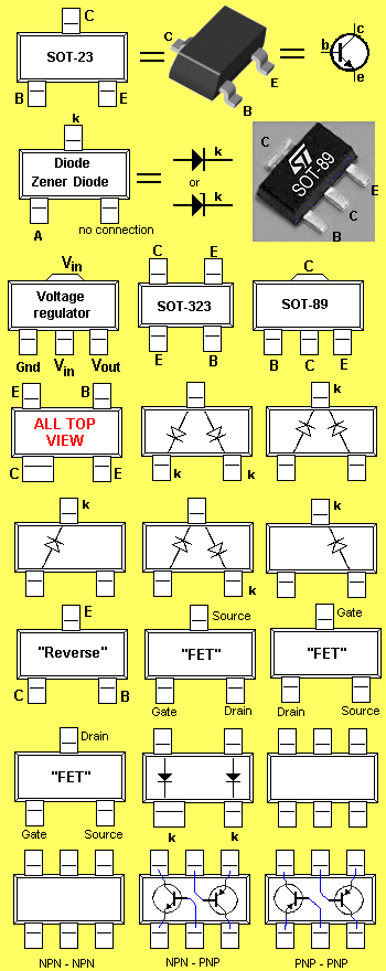
    Yes but in this case it is reversed situation; cathode is left leg and middle leg is anode.
    If you observe "Wave" schematic (Golden Mask is based on it); you'll notice that cathode is going to 3. and 5. pin of LM358 (MC1458 in some schematics) and anode is going to -5v rail.
    It is exactly like that placed and wired on Golden Mask pcb.
    So it is actually reversed from what 2nd image is showing.

    Leave a comment:


  • BILLY
    replied
    Originally posted by ivconic View Post
    It is zenner but according to schematic and how it is wired on pcb; seems it is having quite different pin assignment than standard "BZV.." type!?
    Left leg is cathode, middle leg is anode... and what the hell is right leg?
    Damn "madeinchina" products! Zillion combinations and no rules at all!
    Probably the base or common connection. Used to control the parameter of control by another source. Figured you would know that. Maybe I am missing what you asked. Is what your talking about the 2nd image from top?

    Leave a comment:


  • ivconic
    replied
    It is zenner but according to schematic and how it is wired on pcb; seems it is having quite different pin assignment than standard "BZV.." type!?
    Left leg is cathode, middle leg is anode... and what the hell is right leg?
    Damn "madeinchina" products! Zillion combinations and no rules at all!

    Leave a comment:


  • ivconic
    replied
    Originally posted by Koala View Post
    Bottom of the page has it as a duel diode HSMP-3822. Doubt it will be the only possibility

    http://www.talkingelectronics.com/projects/SurfaceMount/SurfaceMount-P1.html
    I checked it with analogue ohmmeter with scale.
    It shows deflection as npn transistor when black probe is on left leg (usually base at SOT223 transistors).
    But than it also shows some deflection even when red probe is on left leg?
    Some special darlingtons are showing such deflection too. Some fets too.
    Tough to be sure.

    Leave a comment:


  • Koala
    replied
    Bottom of the page has it as a duel diode HSMP-3822. Doubt it will be the only possibility

    http://www.talkingelectronics.com/projects/SurfaceMount/SurfaceMount-P1.html

    Leave a comment:


  • ivconic
    replied
    Originally posted by aothunterpl View Post
    Which components?


    ca7g - semiconductor diode
    ca7g - or it could be the (condenser / capapilator) MKT or Tantalum SMD


    is probably connected to the transistor in package sot or smilar

    regards
    Yes could be tantalum capacitor.
    But what exactly is that SOT223 component? Looks like transistor?
    There is only "F5" printed on it.

    Leave a comment:


  • aothunterpl
    replied
    Which components?


    ca7g - semiconductor diode
    ca7g - or it could be the (condenser / capapilator) MKT or Tantalum SMD


    is probably connected to the transistor in package sot or smilar

    regards

    Leave a comment:


  • ivconic
    replied
    What are these two components?
    Anybody know?


    Click image for larger version

Name:	new-1.JPG
Views:	1
Size:	48.0 KB
ID:	344460

    Leave a comment:


  • amtech2005
    replied
    Happy New Year Everyone !! Looks like Golden Mask is not a project but only for sale. If I am wrong then please post a schematic and pcb link . Thank-you. Regards........ Eugene

    Leave a comment:


  • aothunterpl
    replied
    Hi god job.

    Can you put hear testet & work fine schematic, or sent to PW mesage.

    Thanks.

    Leave a comment:


  • vlamvers
    replied
    here to discuss my device


    Announces a competition - "Make the body" Golden Fleece " - http://forum.golden-mask.com.ua/view...hp?f=28&t=3755

    Leave a comment:


  • württemberger
    replied
    Originally posted by vlamvers View Post
    Good afternoon.
    My mask works, now being tested.
    Best wishes for the new Year

    Now, one year later... is the test finish...
    Works your GM good? So good as the original?

    Leave a comment:


  • aothunterpl
    replied
    Hello frend as you tested of GM Mask
    Something has changed in the scheme. ?

    Leave a comment:

Working...
X