
 Tweet
Tweet
Originally posted by Koala
View Post
-
Not exactly. The TX waveform provides the reference signal for clocking the I & Q demods. If the TX coil is a perfect inductor, either the voltage or current waveform can be used as they are precisely 90° apart. But the coil isn't ideal, it has finite resistance so for best accuracy the current waveform should be used. This is pretty old news, there are designs out there that already do this. -
welcome back AzizComment
-
Thanks to Ghound over on Dankowski's Forum, we have some interesting EMC-testing technical stuff on the Equinox, including the User Manual, and internal PCB photos:
https://fccid.io/Z4C-0022
Images:
https://fccid.io/png.php?id=3643401&page=1
https://fccid.io/png.php?id=3643401&page=2
Curious PCB tracking, reminds me of hand drawn boards, with the sticky-backed tape on clear acetate sheets. Very curvy, like my original Sinclair ZX80 and ZX81 home computers.
Micro looks to be an ST-micro ARM-cored one.Comment
-
Not sure I would use FFC's for the external connectors.Comment
-
Same TX method as White's DFX & V3.Comment
-
Interesting Carl.
Same method, but more frequencies at one time.
Thoughts on that Carl?Comment
-
Part 3: https://www.minelab.com/usa/go-minel...ologies-part-3
What is the benefit of the square waveform? It’s obviously full of higher order harmonics.
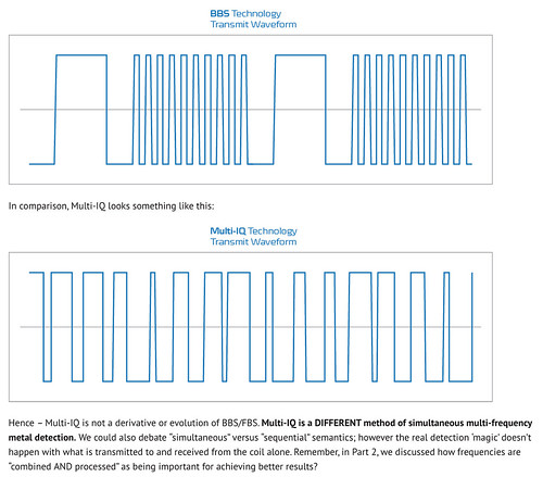
In addition, if the time scales are relative, the wave form at the bottom appears to be higher frequency dominant compared to the BBS waveform above.Comment
-
It is the way to generate different TX frequencies at the same time (harmonics of course).Originally posted by go-rebels View Post
We need to observe TX signal in frequency domain.Comment
-
There are benefits to square wave that are not obvious.
First, there is no 1/f noise in square wave, unlike sinus oscillators that are very problematic in 1/f region, resulting in false targets. Noise and amplitude stability depend only on power supply noise and stability, which is easy to keep very good.
Second, there is no resonant structure you need to pamper, but instead you just hit a coil with brute force at frequency of your choice. This frequency is synchronous with your clock, of course, and you have no problems with jitter, aliasing and whatnot.
Third, and the least expected is efficiency, which may be even better with square wave than sinus. In resonant tanks the recouperation is achieved via current recirculating between a coil and a capacitor, and efficiency is better with higher Q factor, but because oscillator circuitry ruins Q, the efficiency is less than that limited by Q. With square waves, and modern MOSFETs, efficiency is at its peak, limited only by Q. Current recirculates between a coil and large capacitors in power supply, going through low resistance MOSFETs.
As for harmonics, there are filters that fix those in frequency domain, but you may also use raw signal in time domain - depends what you want to achieve.Comment
-
ThanksOriginally posted by Carl-NC View Post
So now we know. Multi-IQ is the same transmission method as used in White's 2002 DFX
Not so much revolutionary as evolutionary.
Time will tell. I expect it to be good. As are all multi frequency machines
Comment
-
It seems my reply, post #2, was pretty close.
I'm not expecting the 'multi-IQ' waveform 'scope traces' to be super-realistic, but what freqs do you think are present in that square-wave? It looks like a 4:1 ratio to me, ie. 5kHz / 20kHz.Comment
-
kellyco lists equinox 600 at 649.00, the 800 at 899.00 https://www.kellycodetectors.com/catalog/minelabComment
-
Hard to tell exactly, but it looks like 3 frequencies. The overall waveform spans the fundamental, and there is definitely a 3rd harmonic term.Originally posted by markg View Post
Davor covered this nicely. In general, a square-wave voltage applied to a coil creates a triangle-wave current (and magnetic field). The target responses can either be demodulated in the frequency domain (DFX & V3) or the time domain (BBS/FBS). Concurrent (simultaneous) multifrequency generally requires frequency domain, so I assume that is what the Equinox will use. As such, all those high-order harmonics get filtered out.Originally posted by go-rebels View Post
More specifically, the TX current, not the TX voltage.Originally posted by WM6 View PostComment
-
I've had a tinker with the waveform image, I think I've pieced together a full cycle of the signal, attached:
It looks like there's a 5:1 ratio. There's a component that appears to have 3 cycles, for 15 cycles of the highest freq component. What else?Comment
Comment