Announcement

Collapse
No announcement yet.

VCO audio

Collapse
X
 
  • Filter
  • Time
  • Show
Clear All
new posts

  • VCO audio

    This could be used as nice audio vco for various projects, of course; suitable for PI detectors.
    There are two versions of hex that i prepared; 0v to 5v at the input and 5v to 0v at the input.
    Most of the diy PI's we have here on forum will be matched with second; the 5v to 0v at the input version.
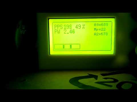
    At the output there is pretty linear 1 to 400Hz audio (on video is up to 300Hz). Can be filtered and amplified on many ways, i am offering only few simplest.
    I picked the range 1Hz to 400Hz because it do the job for me. But i could go up to 8Mhz range. Of course; wider the range = worse the linearity.

    Code is cleaned from LCD stuff, it is only what's shown on schematic.

    Click image for larger version

Name:	VCO.JPG
Views:	1
Size:	81.7 KB
ID:	371187


  • #2
    What you see on video is working version, with 1-300Hz range and 49% duty cycle.
    HEX files are modified; 1-400Hz range and 50% duty cycle.
    Also what you can hear on video is piezo output version. Which is bit rougher.
    8r speaker version is of higher quality of course. Very pleasant tone.
    Even better would be if some amplifier is used, for example LM386 or similar.
    Up from recently we have choice to pick from wide variety of ultra low power D-class power amplifiers, usually sold as micro modules.
    I tested this vco also with this one:
    https://arduino-shop.eu/arduino-plat...fier-2x3w.html
    Can be supplied with 2.5v to 5.5v. Low consumption. With good speaker provides splendid audio.
    (oh... if i only had all this cookies 20-30 years ago!!!)

    Comment


    • #3
      video doesn't work

      Comment


      • #4
        Hello ivconic! I repeat your scheme. Question --- which fuses to expose? Thanks!
        Attached Files

        Comment


        • #5
          Originally posted by ivconic View Post
          What you see on video is working version, with 1-300Hz range and 49% duty cycle.
          HEX files are modified; 1-400Hz range and 50% duty cycle.
          Also what you can hear on video is piezo output version. Which is bit rougher.
          8r speaker version is of higher quality of course. Very pleasant tone.
          Even better would be if some amplifier is used, for example LM386 or similar.
          Up from recently we have choice to pick from wide variety of ultra low power D-class power amplifiers, usually sold as micro modules.
          I tested this vco also with this one:
          https://arduino-shop.eu/arduino-plat...fier-2x3w.html
          Can be supplied with 2.5v to 5.5v. Low consumption. With good speaker provides splendid audio.
          (oh... if i only had all this cookies 20-30 years ago!!!)
          What is its sensitivity in millivolts?

          Comment


          • #6
            The focus of a detector is on the stability of processing amplification. The latter is very easy. If the processing is not processed well, it is almost impossible to make a good instrument

            Comment


            • #7
              Originally posted by SWL View Post
              Hello ivconic! I repeat your scheme. Question --- which fuses to expose? Thanks!
              Usually i don't mind the fuses, since i use Arduino platform to write the code.
              So fuses are default and Atmega works with standard bootloader.
              Also works the same without bootloader.
              However; your question makes sense.
              Lately i buy Atmegas from various sources and i noticed that those are coming with different fuse configuration!??
              So i examined those differences.
              This works for me:
              L 0xFF
              H 0xDE
              E 0xFD
              LB 0xFF

              Comment


              • #8
                Originally posted by SWL View Post
                Hello ivconic! I repeat your scheme. Question --- which fuses to expose? Thanks!
                What software you are using to draw pcb?
                Looks nice and interesting.

                Comment


                • #9
                  Thanks for the answer! I'll put it as you wrote. This is Sprint Layout, just the color scheme has been changed ...

                  Comment


                  • #10
                    Originally posted by SWL View Post
                    Thanks for the answer! I'll put it as you wrote. This is Sprint Layout, just the color scheme has been changed ...
                    Resistors and capacitors are of the shape and style i don't have in my Sprint Layout.
                    Is that custom library?
                    Where can be downloaded?

                    Comment


                    • #11
                      https://drive.google.com/drive/folde...NgnomTyZDZnTY9


                      older ones
                      http://ncdn.ir/index.php?route=blog/...article_id=330

                      Comment


                      • #12
                        Makros.rarHere
                        Attached Files

                        Comment


                        • #13
                          Originally posted by SWL View Post
                          [ATTACH=CONFIG]49541[/ATTACH]Here

                          Comment

                          Working...
                          X