
Hello friends, buy the kit and I put it together neatly and carefully, then check the welds.
I turned it on and had a high pitch, I followed the calibration steps: Connect the positive lead of the multimeter to pin 6 of NE5534P and the negative lead to ground and went to 0Volt.
Before following currencies tried moving but nothing happened, I returned to calibrate and climbed to 1.37 Volt and there if metal detecting ..
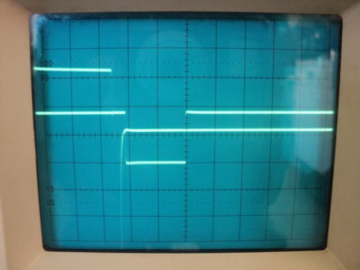
The second problem is that in 0Volt or 1.37 Volt not calibrate the trimmer as Delay, I said it with an oscilloscope, but would help to know what to do.
I also want to know which are the points TP1 and TP2.
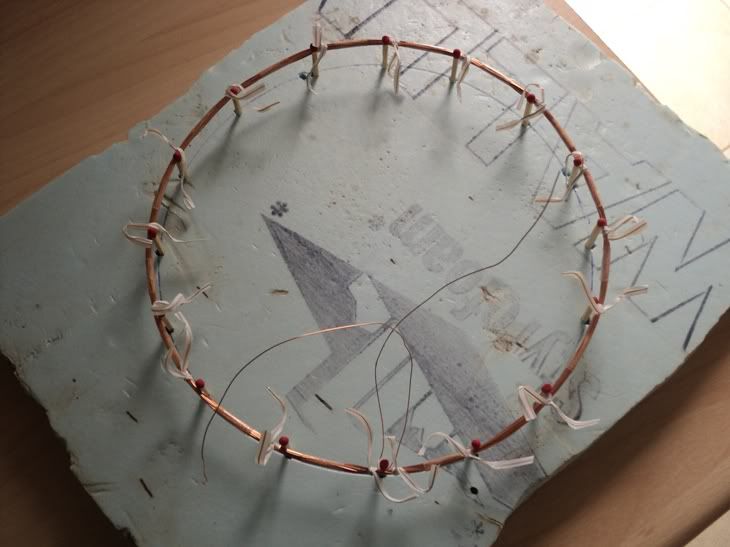
I built 4 coils of different sizes and all they detected up to 2 inches is a roll of copper wire of 400 grams, and an inch is the most that I could detect my gold ring ...
6 days ago I keep testing and do not know how to follow.
Request help and suggestions to finish assembly.
Is there a technical manual?
Thank you very much!
Omar
-
Hi
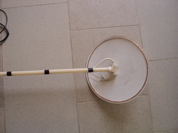
Thanks for the picture, I am always interested in how people connect the rod to the coil
and the handle to the rod, to me this is the hard part of building a detector
somebody always has new inventive ideas.
cheers
6666Leave a comment:
-
Hi,
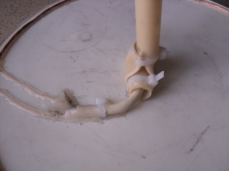
Just heated the detector rod tip and bend it around a little piece to make it ajustble
It as got 2 zip tie to the coil plate and a god amount of hot glue to reinforcement
Leave a comment:
-
Good job, how did you make the rod end its looks commercially made ?
and is it just hot glued to the coil plate ?Leave a comment:
-
Hi,
Final product
I managed to make it lighter than the DEUS from XP only 495.3 grams
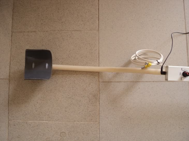
In relation to the depth of detection, managed 27cm for a € 2 coin and around 30cm's for my wedding ring 21mm diameter and 4.2g
I leave just a little video to spark the curiosity .... sorry for the poor quality but my camera is really worthless
http://youtu.be/fzV1UdGoW5gLeave a comment:
-
Hi
Made some progress
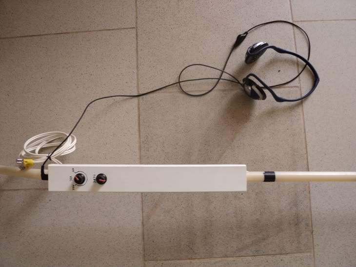
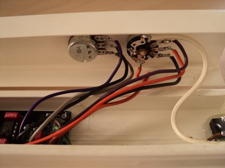
Control box made of rail to pass wires in it
Volume knob, tune and headphones jack placed
Power supply wire to connect to my backpack 4.2A 12V battery
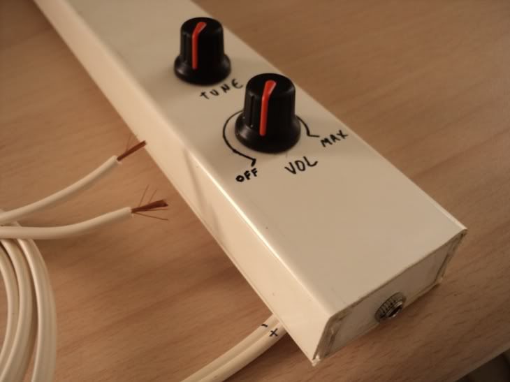
Positive lead of battery interrupted by volume knob
Just need to make the detector rod,.... connect the coil with coaxial cable to the controlbox and isolate it with hot glue
Leave a comment:
-
Hi,
Thank´s for the tips.
I have adjusted my delay properly (delay pot all way clockwise).....And I will use the degaussing coil, is lighter, takes up less space and get the same results.

Time to start making the case for all content
RegardsLeave a comment:
-
Yes careful when you break the seal on a CRT. It contains a thin layer of phosphor paint that will become airborne. It's poisonous if you breath it in.
Best to use a pair of pliers like mentioned but all you need to do is twist the end of the neck off slowly. The slower the vacuum inside the tube is eliminated, the less chance of phosphor release.Leave a comment:
-
congradulations you got it to work first time, like the idea of using degausing wire from a TV, got a few put back here from years ago, that was my secret lol .
.
Another wire you can try which ive used in the past is the wire from the scan coils, most are good quality insulation due to the high influx of voltage and current they had to handle, far in excess to what we are using them for.
You will find theres two lots of windings, the heavy gauge was fed from the line output stage of the TV that gave you the horizontal scan, the lighter windings was driven from the frame output stage which gave you vertical scan.
So for your PI go for the linescan side of the coils which are used to handling around 1000v.
If you got the whole TV and its plastic remember you can make good project enclosures out of them, ive just used part for my Mini pulse 3 im building.
Also alot of the older TVs used 32-35ohms speakers which are handy with alot of projects on here not to mention the wiring looms, plugs sockets switches etc.
And while your striping it check inside the tuner assembly, you maybe lucky and find a BFR199 inside which with that and the housing will build you a very nice universal coil tester which I posted the full project on here.
Word of warning, be careful with the tube as they will implode if you drop it on its face.
If you feel the need to discharge it just knock the neck off with pliers or something.
All the bestLeave a comment:
-
Hi,
Thank you all for the tips
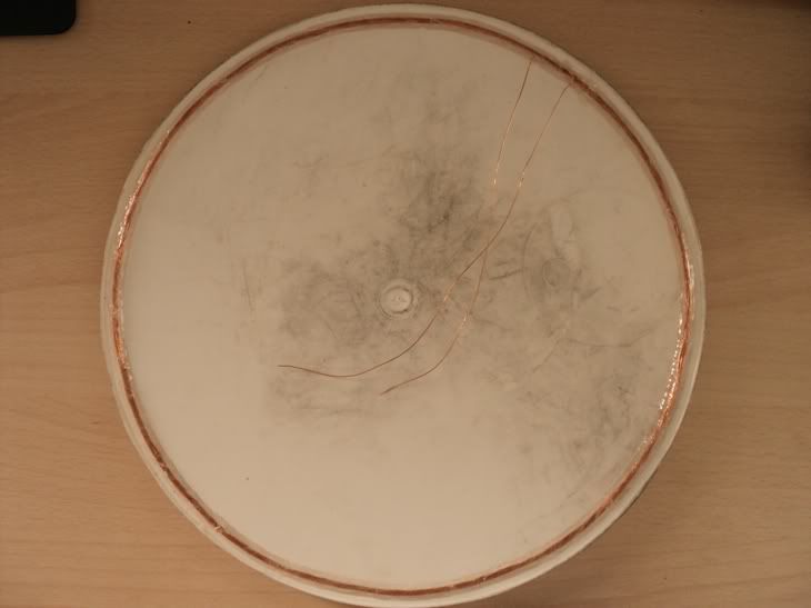
Made a coil with degaussing wire from Tv set with 21 turns, 25cm diameter and 2.7Homs (too high).....I hit an Euro coin 25cm in air test
Power consumption was
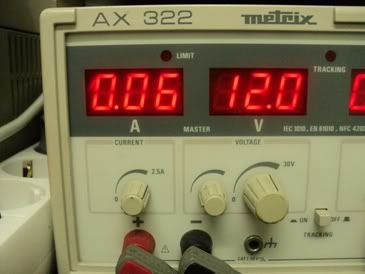
Them made this one with speaker wire 12cm ID, 25cm OD, 20 turns and 0.2Homs.....also 25cm for an Euro coin

Energy consumption increased significantly
I'll try to redo this coil with single wire to increase Homs and reduce weight
RegardsLeave a comment:
-
you may have too many turns on your coil, try about 21 turns
see here http://www.geotech1.com/forums/showthread.php?t=19051
and here for delay help http://www.geotech1.com/forums/showt...t=17240&page=2Leave a comment:
-
Hi,
Thank you so much 6666
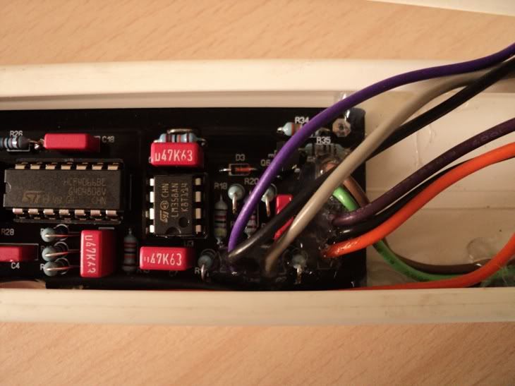
Ed in SoDak I have all coponents in the rigth place .... even the wire bridges near the IRF and C6
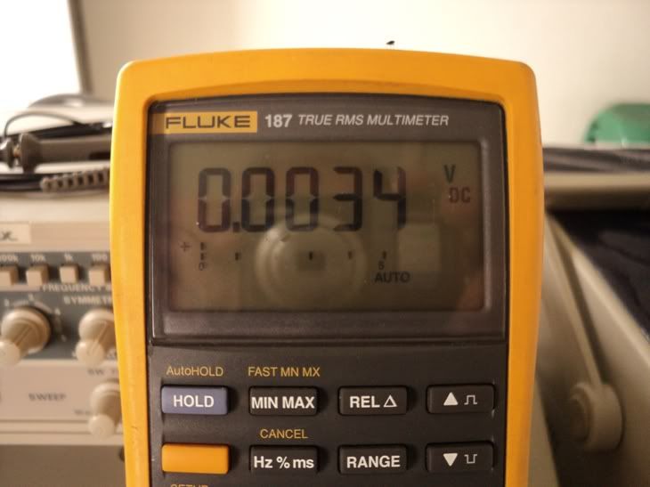
My multimeter ground lead was in the wrong place now I have zero Vdc under pin 6 of the 5534
How can I adjust the delay pot with my scope....
What are the best specs for the coil,... coil diameter / wire AWG / PVC stranded wire or single Enamelled wire / homs to achieve
Best regards
NezocasLeave a comment:
-
The 2 IC's facing each other is ok, thats just the pcb layout,
what works for me is the digital multimeter negative lead on battery ground
and the positive lead to pin 6 of the 5534, you should be able to adjust it
to zero volts.Leave a comment:
-
Your assembly looks good in the pic, but check for solder bridges on the other side. I am not familiar with this circuit, but it is more normal for the ICs to point the same way. In the pic where you show the two calibration hooks, the two ICs have the index facing each other. Is one perhaps incorrectly inserted in the socket?
-EdLeave a comment:
-
Hi,
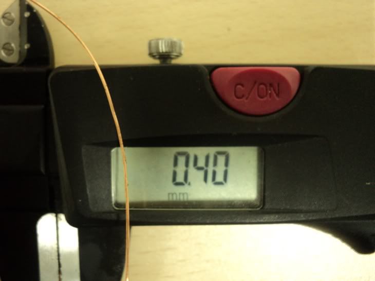
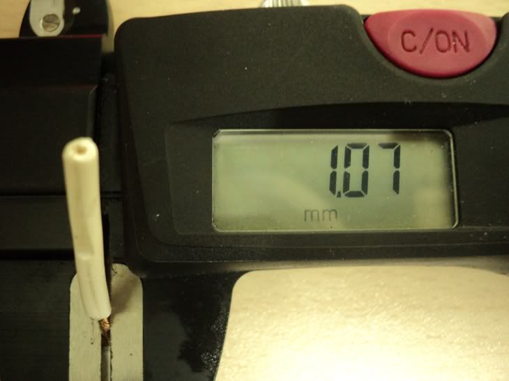
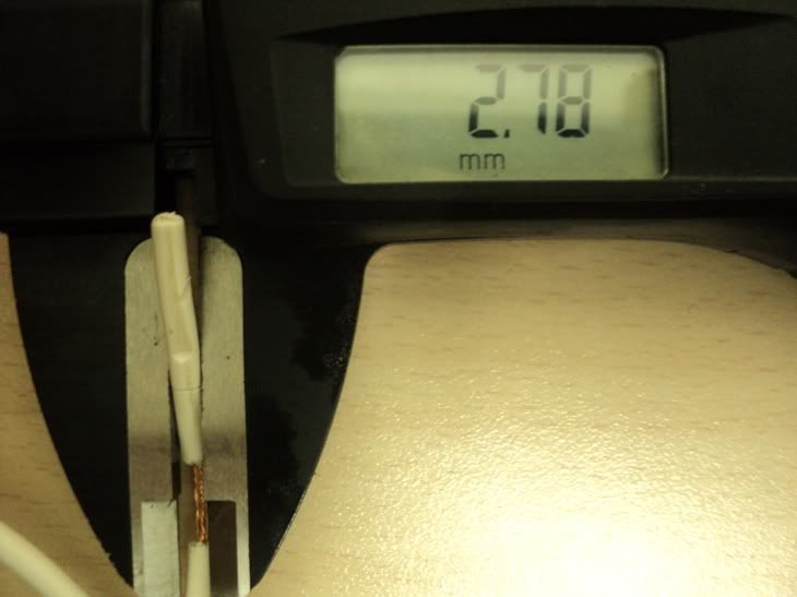
Made a quick coil with 0.40mm wire 200mm diameter 30 turns and 3.5homs
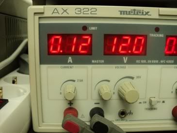
Connected the board to a 12V supply, and I cant get under 1.4Vdc with offset pot...ground lead was on TP1
Under pin5 of the 7660 I got -4.61Vdc, ground was on IRF casing
A little help would really come in handy
Regards
NezocasLeave a comment:
Leave a comment: