Announcement

Collapse
No announcement yet.

help with surf pi, trying to make it work!!

Collapse
X
 
  • Filter
  • Time
  • Show
Clear All
new posts

  • help with surf pi, trying to make it work!!

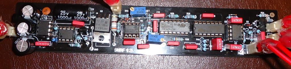
    hello everyone, am new at this, am currently building a surf pi from silverdog and i need some help, i assemble the pcb,
    i get on ic 7660 pin 5 -5.06v and +5.06,
    am trying to adjust
    offset to give 0v at TP2 (ne5534 pin 6)
    Am putting red on tp2 (or pin 6) black on ground, I turn pot for offset and nothing happens. i have reading 1.92v. can i get some help?? Tp2 is 0.92v
    Coil is 20cm diameter, 17 turns 1.5ohm, coppers wire 0.5mm or 0.3mm am not sure, shield. I also have an antenna coil
    I also have an antenna coil 20cm diameter, 24 turns 3,3ohm.

  • #2
    Hi,

    Red lead on TP2 (pin6 of 5534) and black lead on battery ground output
    Have you made the jumpers near R5 R8 and C6

    Comment


    • #3
      Originally posted by Nezocas View Post
      Hi,

      Have you made the jumpers near R5 R8 and C6


      yes everything is in order
      .

      am trying to attache or paste my photos but it keeps saying The connection was reset

      sorry. thanks for replying

      Comment


      • #4
        Upload them to photobucket and them copy the link and paste it in your topic reply

        Comment


        • #5
          A private space for your group's photos and videos. Share, react, and relive moments together. Available on iOS, Android, and desktop. Free for new sign-ups.

          A private space for your group's photos and videos. Share, react, and relive moments together. Available on iOS, Android, and desktop. Free for new sign-ups.

          Comment


          • #6


            Comment


            • #7
              Does your IRF body touching the ground jumper wire

              Comment


              • #8
                Originally posted by Nezocas View Post
                Does your IRF body touching the ground jumper wire

                no no its ok.

                Comment


                • #9
                  Originally posted by pavlos_x View Post
                  no no its ok.

                  Hello Pavlos.

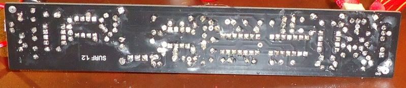
                  The best you can do first is to clean the solderside with cleaning alcohol, then check your solder work carefull ! On the photo it looks like that it needs some inspection ?


                  Best regards.

                  Ap

                  Comment


                  • #10
                    i cleaned everything, everything seems to be in order. i was talking with silverdog and he said

                    ''Measure voltages on Ne5534 pins 2 and 3, when metal is placed in coil there should be some change
                    If you see change at 2 or 3 but not 6 then 5534 is faulty
                    If you see no change something is wrong in coil circuit, irf9640, 555, 2n3906''

                    so this is my response


                    ''No changes at all, I checked for pin 2 + 3 voltage is 0.37v (same for both with or without metal in coil) 6 is 3.55v (before it was smaller 1.92v I don’t know what happen and it got higher).''

                    i went and i bought the parts again, am waiting to see if am gona change them or not, all of these happened because i had some ic's in the wrong way

                    Comment


                    • #11
                      does anyone now or have a chart on what voltages i should be getting in each component?

                      Comment


                      • #12
                        Originally posted by pavlos_x View Post
                        does anyone now or have a chart on what voltages i should be getting in each component?

                        With coil connected the current taken from the power supplay has to be around 50 mA have you checked that?

                        Comment


                        • #13
                          i have 90mA

                          Comment


                          • #14
                            Originally posted by pavlos_x View Post
                            i have 90mA

                            Thats to much... if no audio is on ! . Best remove all IC out there sockets ..accept the ICL7660. Then check if you have the right volts on the supplay pins from the IC's has to be , +5 volt and -5 (wil be lower I think , ca. -4V as I remember)

                            and see how much current is taken without the ic's
                            Last edited by ApBerg; 05-17-2012, 03:58 PM. Reason: ad some text

                            Comment


                            • #15
                              without audio i have 0.37mA. with no Ic on i have 0.01 mA and onthe pins 6 and 8 i have -5.08 and +5.08

                              Comment

                              Working...
                              X