Announcement

Collapse
No announcement yet.

Replies to Minipulse Plus

Collapse
X
 
  • Filter
  • Time
  • Show
Clear All
new posts

  • Originally posted by surfdetector View Post
    What Commercial coil are you using?
    The easiest way to find the correct damping resistor is to build yourself a damping resistor jig. I have a video on my Youtube channel that outlines it for you.
    Hi Dear Master Surfdetector,
    i wasn't able to find your video regarding the damping resistor jig.
    i did found this one, regarding coil connection to pcb.

    i intent to make a homemade coil, so far i get to this sketch, following your video. However, i'm not sure how to join S/F/B/G.
    Can you help this NEWBIE?
    Much appreciate for you time.
    Best regards,
    Click image for larger version

Name:	MPP coil connection.jpg
Views:	1
Size:	50.1 KB
ID:	362401

    Comment


    • Originally posted by Coolmakina View Post
      Hi Dear Master Surfdetector,
      i wasn't able to find your video regarding the damping resistor jig.
      The name of the Play List is Damping Resistor

      Comment


      • Originally posted by surfdetector View Post
        The name of the Play List is Damping Resistor
        Thank you. Appreciate that.
        But, i don't understand where are you scooping.
        I understand the jig, the resistors + por assembly,.
        But i have no idea where you out your scoope on the second v?deo.
        I am trully sorry. I am just an assh**e o thought that i could just by the boards, solder some stuff and the Child would born.
        I am a self learner but this is taking me hours of living.
        I can't sleep. I just read, read, read...try, try, and the more i read and try, the more i get confused.
        ����

        Comment


        • Originally posted by Coolmakina View Post
          Hi Surf
          I have a 11" DD from a old tx850.
          The TX850 is a VLF metal detector, so the coil may not be suitable for a PI.
          I would advise that you do your testing with a mono coil in order to keep things simple.

          Originally posted by Coolmakina View Post
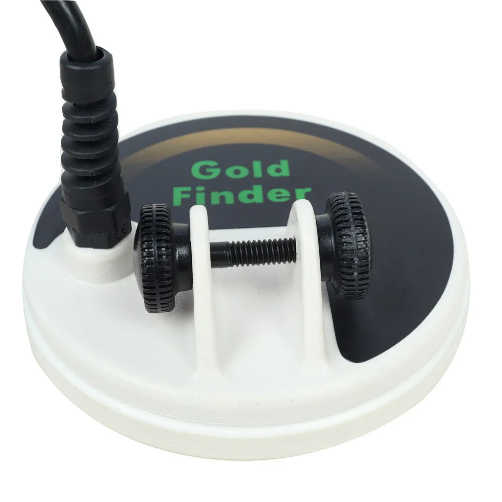
          And a small gold finder
          Mono cool. Bougth from Alibaba.
          What are the details of this coil?

          Comment


          • Originally posted by Qiaozhi View Post
            The TX850 is a VLF metal detector, so the coil may not be suitable for a PI.
            I would advise that you do your testing with a mono coil in order to keep things simple.


            What are the details of this coil?
            Honor to you, sir.
            This is the mono cool i have.
            I am not near the cool, i am out for dinner.
            Tomorrow i can give more details.
            Underground Gold Detector FS2 Small Coil 5 Inch Disk Deep Search Metal Detector Coil Parts for Small Gold in online-store aliexpress.com. Large selection of Measurement & Analysis Instruments Tools in United States, United Kingdom, India, Germany, Ukraine, Australia, Canada, France, Sweden, Italy, Netherlands, Poland, Indonesia, Malaysia, Philippines, Spain, Brazil, Thailand, Turkey, Romania, Singapore, Greece, South Korea, Hungary, Mexico, Pakistan, Belgium, Japan, Vietnam, South Africa, Czech Republic, United Arab Emirates, Hong Kong, Switzerland, Portugal, Bulgaria, Saudi Arabia, Iran, Slovakia, Finland, Denmark, Ireland, Israel, China, Taiwan, Norway, Egypt, New Zealand, Croatia, Austria.

            Comment


            • And i am thinking on build some cool since i don't have the tools to measure the ones i have. Even so, i Need to understand the connections.
              Thank you.

              Comment


              • Originally posted by Coolmakina View Post
                Honor to you, sir.
                This is the mono cool i have.
                I am not near the cool, i am out for dinner.
                Tomorrow i can give more details.
                https://imall.com/product/Undergroun...68-20277844/en
                Unless I'm mistaken, I don't think that it's a mono coil.

                Comment


                • That's a clone of the Fisher Gold Bug coil. 19kHz VLF.

                  Comment


                  • Originally posted by Carl-NC View Post
                    That's a clone of the Fisher Gold Bug coil. 19kHz VLF.
                    Hello Mr. Carl,
                    Yes it is.

                    Comment


                    • Originally posted by Carl-NC View Post
                      You can make a simple square wave oscillator from a 555 timer circuit or a single opamp. Lots of info on the Internet for this.
                      I was able to draw this scheme.
                      I Will try to out this in to a proto-board or so.
                      Click image for larger version

Name:	IMG_20220128_162658.jpg
Views:	1
Size:	915.8 KB
ID:	362408

                      Comment


                      • Hi everyone,
                        i'm still stuck on this step 4 of the minipluse plus.
                        i started 5 units pcb, i wantend to build 5 minipluse plus. Along the way, 1 unit 79L05 was soldered backwards and still aside, It can be fixed later.
                        i was able to do step 1, 2 and 3 on the others 4 pcb's.
                        however i'm frozen at step 4.
                        i bought a hantek 6022be digital oscilloscope to help me out. it's not a great machine but i could afford.
                        the think is i don't have a large money fund to buy a decent one and a signal generator to proper calc the coil inductance and determine the damping resistor R4.
                        so i dig Surfdetector videos, (thanks's surfdetector!), and i built a damping jig as he described.
                        i also built a basket weave coil, according other threat's in this forum.
                        but i not reading the 350V flyback on my scope.
                        my probe and scope software is set to 10X, but peak to peak i only see 10,7V. and kind of a square wave trought the damping jig.
                        i toke some photos but i computer is crashing when i try to upload them.
                        is there any "check" i can make to see what is wrong with my step 4?

                        Comment


                        • Originally posted by Coolmakina View Post
                          Hi everyone,
                          i'm still stuck on this step 4 of the minipluse plus.
                          i started 5 units pcb, i wantend to build 5 minipluse plus. Along the way, 1 unit 79L05 was soldered backwards and still aside, It can be fixed later.
                          i was able to do step 1, 2 and 3 on the others 4 pcb's.
                          however i'm frozen at step 4.
                          i bought a hantek 6022be digital oscilloscope to help me out. it's not a great machine but i could afford.
                          the think is i don't have a large money fund to buy a decent one and a signal generator to proper calc the coil inductance and determine the damping resistor R4.
                          so i dig Surfdetector videos, (thanks's surfdetector!), and i built a damping jig as he described.
                          i also built a basket weave coil, according other threat's in this forum.
                          but i not reading the 350V flyback on my scope.
                          my probe and scope software is set to 10X, but peak to peak i only see 10,7V. and kind of a square wave trought the damping jig.
                          i toke some photos but i computer is crashing when i try to upload them.
                          is there any "check" i can make to see what is wrong with my step 4?
                          all parts checked and they are as spec, except that i have installed IRFS840B instead of IRF840....could this be the cause?

                          Comment


                          • IRFS840B should be fine.

                            Comment


                            • Click image for larger version

Name:	IMG_20220212_141236.jpg
Views:	1
Size:	989.1 KB
ID:	362458Click image for larger version

Name:	IMG_20220212_141109.jpg
Views:	1
Size:	481.1 KB
ID:	362459Click image for larger version

Name:	IMG_20220212_141035.jpg
Views:	1
Size:	535.2 KB
ID:	362460Click image for larger version

Name:	IMG_20220212_141012.jpg
Views:	1
Size:	674.7 KB
ID:	362461

                              Comment


                              • Originally posted by Carl-NC View Post
                                IRFS840B should be fine.
                                Unless they are bad.
                                Seen a v?deo teste where testing with mult?meter set to diodo i shouldnt see voltage going trougth g and a of the MOSFET. Mines are ****fting voltage both ways. I think i Will replace them..
                                Any others ideas?

                                Comment

                                Working...
                                X