Announcement

Collapse
No announcement yet.

Analog Target Indicator for VLF

Collapse
X
 
  • Filter
  • Time
  • Show
Clear All
new posts

  • Nandor
    replied
    Thats a nice idea man. I have found a few Minelab ID meters on the net for sale. Would be interesting to see the schematic and the pcb and how it works.
    For now I am happy with the needle meter .

    best regards

    Leave a comment:


  • Altra
    replied
    Great work! These retro circuits are interesting to study and build.

    Have you hooked a digital volt meter to the output? It would give you ID numbers for each type of target. The Minelab Sovereign did this using a digital panel meter.

    Thanks for posting


    Leave a comment:


  • Nandor
    replied
    Thank you my friend , you gave me a very good idea about the log amps. I tried it and it works now!
    Also tested some Us coins I have, Monticello Nickel 5.2 and US Dime 7 out of 10 .
    Disc potentiometer is set to barely "touch" aluminium foil. Distance between the coil and the targets does not really effects vdi number, swept speed is more important.

    I would like to find a proper housing for it and if possible a smaller new Meter. It would be nice to find something like Whites analog meter, this part is very important.
    Also it has to be ampermeter or voltmeter? Maybe Carl can share some specs and info on the Whites meter.

    regards

    Leave a comment:


  • dbanner
    replied
    Splendid job! Nicely done.

    Leave a comment:


  • Nandor
    replied
    Click image for larger version

Name:	AnalogVDI1.3.bmp
Views:	2
Size:	102.2 KB
ID:	361539This is the schematic I used. Little changes to the original circuit: BC547 for the Log Amps, 470pF instead of 330pF capacitors, VDI low range trimmer is now connected to minus rail instead of ground for more voltage setting, 1uF capacitor in the Sample&Hold part instead of 470nF and 100uF for the Meter not 22uF as in original schmatic. I will upload in the future some scope pics of the circuit.

    Leave a comment:


  • Nandor
    replied
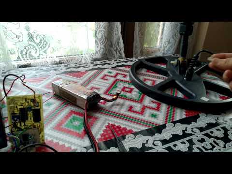
    It's alive and kicking finally!

    Here is the test video of my final version. Did some modifications to the original schematic I used that was shared by Mr Gurdal. Working pretty good, maybe treshold level should be adjusted a bit more for better range.

    regards

    Leave a comment:


  • dbanner
    replied
    Some Flip Flop action going on here.
    Attached Files

    Leave a comment:


  • Carl-NC
    replied
    Originally posted by Nandor View Post
    Well intersting result, I detected many times with my friends Whites 6000 Di PRO SL and it's much slower in response than my TGSL. Almost static like pinpoint channel and the outputs of the filters were very different,
    The 6000 series are 4-filter machines and the TGSL is 2-filter. So, yes, they are very different.

    Leave a comment:


  • dbanner
    replied

    Leave a comment:


  • dbanner
    replied
    That's interesting. I thought that full wave switching would allow faster sweep speeds, allowing bandpass filters to be shifted higher. Yet your experience with 6000DI indicate opposite. Maybe I misinderstand.
    I'm almost done building my circuit. I hope the meter at least show some deflection when I pass a coin over the coil!

    Leave a comment:


  • Nandor
    replied
    Well intersting result, I detected many times with my friends Whites 6000 Di PRO SL and it's much slower in response than my TGSL. Almost static like pinpoint channel and the outputs of the filters were very different, I should have took some oscilloscope screen shots . Anyways the TGSL has 7.23Hz to 15.39Hz. When experimenting with my prototype pcb I also noticed that coins speed over or under the coil affects the accuracy of the VDI. A nice constant medium speed gave the best result in VDI.
    The potentiometer for IDX is a must I forgot to put in on the schematic to set the minimum point for VDI but connecting the pcb to TGSL doeas not needs potentiometer. The best setting would be at small aluminium foil disc level.
    If you look at the filter response with o-scope when foil is detected Geb channel gives bigger amplitude than Disc channel like it's iron the only difference that there is no phase difference between the 2 signals because aluminium is paramagnetic.

    Leave a comment:


  • dbanner
    replied
    TGSL bandpass filters are around 10Hz center frequency.
    The both channels are identical in frequency, phase and gain characteristics.

    The 6000D series it is 20Hz

    I don't know off hand the bandpass frequencies for the 6000DI, but this is easy to know(Ltspice, Filter pro, Tina-TI, etc. The channels are identical, so the gain of XF and YF are identical, and so will be the filter characteristics.

    Changing the component values and gain of the target ID preamp circuit to assimilate with the TGSL I don't think is a big deal. But maybe there are other things to consider.

    Such as the ampltude, since we are taking ampltude measurements for each channel and taking log(y/x). The 6000target ID circuit will work, the meter will deflect. What you make of this is for experimenting.
    Eduardo schematic I saw a potentiometer at the beginning of the preamp.

    Leave a comment:


  • Nandor
    replied
    I have shared these files, pcb and schematic they are done by Eduardo. He did it with LED's, it is the Classic ID series LCD vdi patent.
    About the 6000 series VDI, when I repaired one also measured the filter outputs before the logamps, those 100 micro caps. These filters have a way different output, compared to TGSL or IDX 6000 series filters feels almost static very slow. So I don't think that it would work good with the TGSL's filters.
    Big Bud pro would be a good option, I am working on my little pcb for the schematic I posted, try to finish it soon so I can share my work and progress.
    Best regards

    Leave a comment:


  • Carl-NC
    replied
    Originally posted by Altra View Post
    Another interesting approach without a micro. Uses comparators to measure the ratio of X and R.

    https://patentimages.storage.googlea.../US6421621.pdf
    Back in the olden days before TID this is how variable disc was done. Put a pot between X and R and vary it to set the accept-reject point.
    The patent above "digitizes" the pot and creates multiple discrete TID points. You pick the resistor values to determine where you want those points to be. It's called "flash phase" analysis because it exactly emulates how a "flash ADC" works.
    Another way to do it is to digitize the X & R signals into a micro and do everything in code. Way more flexibility, and is how modern designs do it.

    Leave a comment:


  • dbanner
    replied
    Originally posted by Altra View Post
    Another interesting approach without a micro. Uses comparators to measure the ratio of X and R.

    https://patentimages.storage.googlea.../US6421621.pdf
    Yes, I remember that patent. Never got around to making it. But I remember someone had made it using LED and posted a video. Seems to have worked pretty good.

    The Big Bud also is using comparators in the meter circuit along with some sequential switching.
    This method apparently worked quite good.

    Leave a comment:

Working...
X