Announcement

Collapse
No announcement yet.

Analog Target Indicator for VLF

Collapse
X
 
  • Filter
  • Time
  • Show
Clear All
new posts

  • Nandor
    replied
    Hello
    You are right, it's my fault but the lay file is not affected! Never hurry with a work.
    I hope you can do your project and post your results here. The sensibility of the circuit is pretty good and with the Disc pot set at 4 just a bit below foil discrimination works the best for me.

    Leave a comment:


  • Op04
    replied
    Sir Nandor, I see error on the V1.3 schematic pin no 4 (U2a) should be connected to V+ reverse with pin 11 ??

    Leave a comment:


  • Nandor
    replied
    Thank you for the kind words Op04 .
    It still needs a little noise reduction. I have started to make a TGSL pcb with the VDI incorporated on it with the same size 100x100mm. Those many cables are the noise sources.
    Sensitivity is about 80% compared to the air depth of the search coil.
    Well im pleased with it, noise reduction can wait till winter.

    best regards

    Leave a comment:


  • Op04
    replied
    Originally posted by Nandor View Post
    Here it is mounted on my TGSL.
    It's a nice project.
    Incredible!! You did very good job... and Many thanks for the layout!

    Leave a comment:


  • rajesh
    replied
    Originally posted by waltr View Post
    Remember that the TGSL circuit uses a Comparator, U106a & b, to indicate a good target. It is only when both input to U106 are above the comparator's reference (sen. pot) that the audio is triggered. Iron targets will have either the GB or the Disc channels outputs of U104, U105, go lower.

    If you are picking off the outputs of U104 & U105 to produce an analog signal to drive a meter, then both iron and non-iron will cause meter movement. Maybe you need to have a DC Bias to put the meter needle at center with No target. Then non-iron moves one direction and iron the other direction indicating positive and negative phase of the GB verse Disc channels.

    Not sure how you would get "king of ground cancel' with this.

    Another thought I have once circuit works:
    The analog signal could also be an input to a audio VCO. Then there will be a varying audio tone indicating target types. Probably would want the audio out be gated with the comaprators (U106) so audio is quite with no target.

    Click image for larger version

Name:	5b6db978804941126cc7379f-large.jpg
Views:	1
Size:	113.9 KB
ID:	362033

    Leave a comment:


  • Nandor
    replied
    Here it is mounted on my TGSL.

    It's a nice project.

    Leave a comment:


  • Nandor
    replied
    My bad ! Yes the bases must have to be connected to ground.
    Thanks for telling me!

    regards
    Attached Files

    Leave a comment:


  • dbanner
    replied
    Originally posted by Nandor View Post
    Just made another pcb for the IDX PRO and I discovered that there are errors in the new lay file that I posted earlier so after some corrections and modifications here is the corrected version.
    IDX separates better nickel coins from silver coins than TGSL but hammered coins fall in the lower end of the meter like foil.
    Nandor, please recheck your PCB layout. Some things look strange, for example, the base legs of the two transistors are connected to different points. Is this as you intended? Also recheck the power supply rails.

    Leave a comment:


  • Nandor
    replied
    Here is the schematic image with 8 oscilloscope shots of all the important test points. Target is 1 Euro coin distance is close and the coil is White's Blue Max 950.

    regards
    Attached Files

    Leave a comment:


  • Nandor
    replied
    Just made another pcb for the IDX PRO and I discovered that there are errors in the new lay file that I posted earlier so after some corrections and modifications here is the corrected version.
    IDX separates better nickel coins from silver coins than TGSL but hammered coins fall in the lower end of the meter like foil.
    Attached Files

    Leave a comment:


  • Nandor
    replied
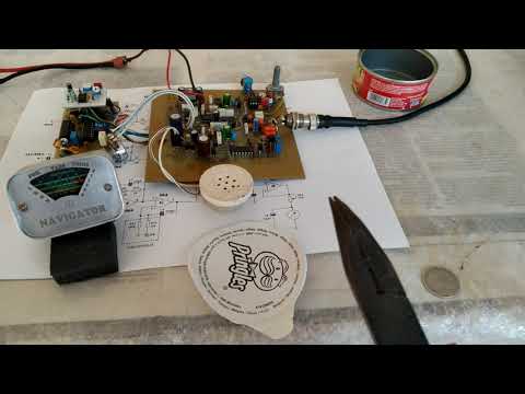
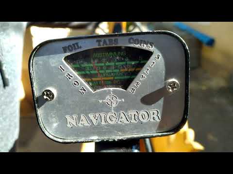
    It's almost ready to use, needs to be painted and mounted on my TGSL detector .

    I used an old car relay for housing and made the front panel with laser a engraver.

    Leave a comment:


  • dbanner
    replied
    Analog 1mA meter is connected in parallel with circuit as voltmeter. Series trim resistor adjusts meter high end

    20 led voltmeter in dot mode using two LM3914, perhaps could make a good display.
    Attached Files

    Leave a comment:


  • Nandor
    replied
    I can't figure it out . On the weekend I will try share another video and some pics with the probes connected to the test points.

    regards!

    Leave a comment:


  • dbanner
    replied
    Member Davor had designed this circuit a long while back. Thanks to him for posting his work.
    Attached Files

    Leave a comment:


  • Carl-NC
    replied
    Originally posted by Nandor View Post
    It would be nice to find something like Whites analog meter, this part is very important.
    Also it has to be ampermeter or voltmeter? Maybe Carl can share some specs and info on the Whites meter.
    It's a 1mA meter.

    Leave a comment:

Working...
X