
-
Here is the wring for the normal GB and the coarse/fine GB:
You might be able to get away with a single twisted pair instead of dual coax. If so, pins 2 & 4 will not be connected.
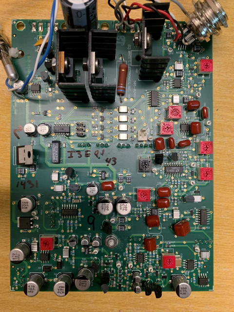
I think the connector on the component side has to do with factory calibration, but I don't remember what was plugged in.Leave a comment:
-
Hi Carl,
Thanks, I understood that, sorry I may have misspoken.
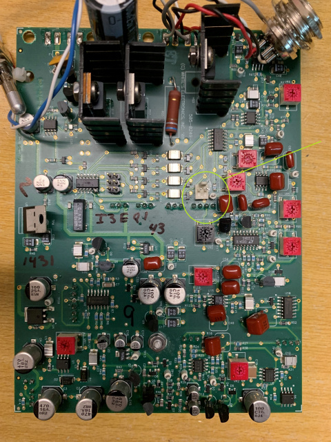
The part I don't understand is the wiring of the 10k part (not On-Off). Because on the white connector P10 (4 pins) of the Ground Balance I will come to connect my 100K potentiometer to it.
But how do I also connect the 10k to it if I understand correctly?
The connector I am talking about is the one on the other side, it is located above the P10 GB connector, is it related to the 10K GB Fine ?
Thanks.Leave a comment:
-
You want to get a potentiometer that has a built-in on/off switch. It will have the usual 3 lugs for the pot, plus 2 extra lugs (usually on the back) for the switch:Originally posted by Melano87
Pot switches are mostly limited to SPST-type and the GB switch in the TDI is a SPDT-type. To make the SPST work properly you will need to add a 100k resistor, like this:
Then 2 of the 3 pot legs are used for the GB pot. The third pot leg is not used.
I don't know what connector (on the other side) you are referring to.Leave a comment:
-
Hi, thanks.Originally posted by sinclairuser View Post
Yes, I was able to pick up this new card at a low price, never served at a Whites retail store in France.
Having a coil, I wanted to reassemble it as factory, I just have to find a case now.
Even if I had tinkered with the TDI SL, Tesoro, Sovereign I didn't want to do bull**** with this Pulse Scan. The explanations cannot be found on the Internet. I won't touch anything else on the card.Leave a comment:
-
good luck, i would not "tweak" any of those red pots on the board.
it doesn't look like they have been moved which is good, if they are "factory" all your work is mechanical assembly.
having to "setup" the machine may be a stretch for you going by your questions, if you want to modify the TDI thats great but i would wait until you have it functioning properly.
modifying a working unit is easier than doing a non working one simply because you could introduce faults, if it works and you tweak something and stops functioning then your mod caused it, so reversing the mod should put it right.Leave a comment:
-
For Threshold, Frequency, and Delay pots connect the middle lug to the middle pin. The outer lugs can be connected backwards but you will know it when you turn the knob. LED also has polarity; it works one way and doesn't work the other way.Leave a comment:
-
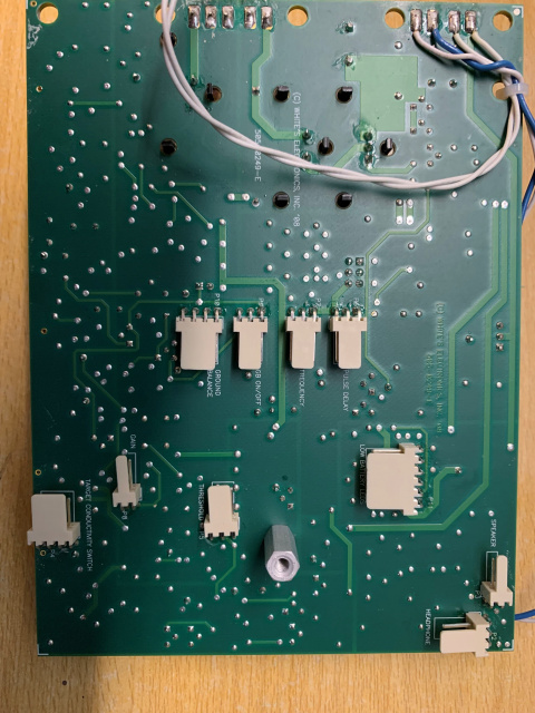
So the two internal wires of the "conductivity switch" connector are not to be wired, if I understand correctly.
They are used for grounding the coax shields, this is for EMI suppression. You might get away with using a single twisted-pair connection to pins 1 & 4.
For the Gain, how does it connect to the potentiometer because there are only 2 terminals (not 3) on the white connector?
Connect to the middle lug and one of the outside lugs. If rotating the pot clockwise makes the gain decrease then you picked the wrong outside lug.
The same goes for the Ground Balance, 4 terminals, the two wires in the middle are to be put on the same terminal in the middle of the associated potentiometer ?
The GB pot connects as follows:
Pin1: outside lug of pot
Pin2: shield ground
Pin3: middle lug of pot
Pin4: shield ground
Again, try twisted pair to just pins 1 & 3.
And the ? GEB On-Off" which is originally a switch, we just have to connect the 3 terminals of the white connector to a potentiometer (keeping the central terminal in the middle at each end)?
No, you connect pins 1 & 2 of P9 to a switch that is part of the GB pot. You will also need to add a 100k resistor between P9 pins 2 & 3.Leave a comment:
-
Thanks once again.Originally posted by Carl-NC View Post
It's Weird (laughs).
So the two internal wires of the "conductivity switch" connector are not to be wired, if I understand correctly.
For the Gain, how does it connect to the potentiometer because there are only 2 terminals (not 3) on the white connector?
The same goes for the Ground Balance, 4 terminals, the two wires in the middle are to be put on the same terminal in the middle of the associated potentiometer ?
And the ? GEB On-Off" which is originally a switch, we just have to connect the 3 terminals of the white connector to a potentiometer (keeping the central terminal in the middle at each end)?Leave a comment:
-
It took me a while to recall the weirdness in the Mode switch but here it is:
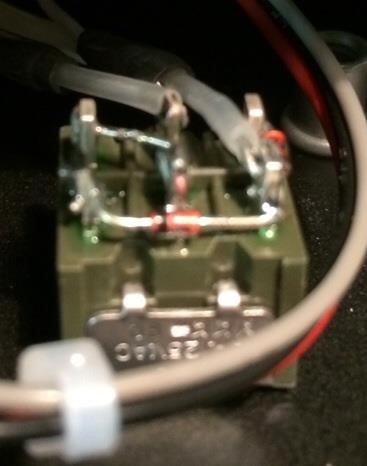
The diodes are normal 1N4148 type, not zeners. The switch is what is weird, it is a DPDT "on-on-on" type. Here is the operation:
High: 1 & 2 are closed
All: 2 & 3 are closed (or maybe it's 1 & 4, it'll work either way)
Low: 3 & 4 are closed
There are 2 wires needed but the photo shows that both wires are shielded which is why the connector has 4 pins.
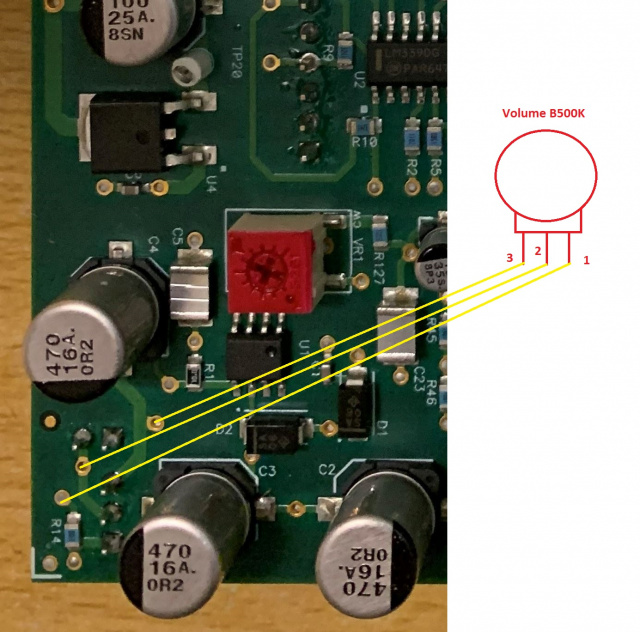
On the volume control, the trimpot VR1 is the volume control. You can remove it and replace with a control pot. Should be 5k.Leave a comment:
-
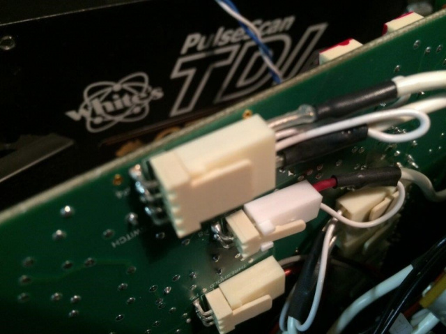
I came across photos on another forum showing the wiring of connectors and switches on the Pulse Scan. (The photos are like this on the site, not of very good quality)Originally posted by Carl-NC View Post
Is the wiring of the conductivity switch just unlikely?
I have the impression that on the white connector the two wires in the middle are connected via a zener diode (Threshold & Gain too...?) One on the wire on the right and one on the wire on the left... I don't understand anything.
Is it possible to mount a potentiometer for the volume like this?
Leave a comment:


Leave a comment: