

Originally posted by Melano87
View Post
-
I had forgotten, the Mode switch has some weird wiring. I think it's a DPDT-center-off (6 lugs) but I'll need to open up a TDI to see how it's wired.Leave a comment:
-
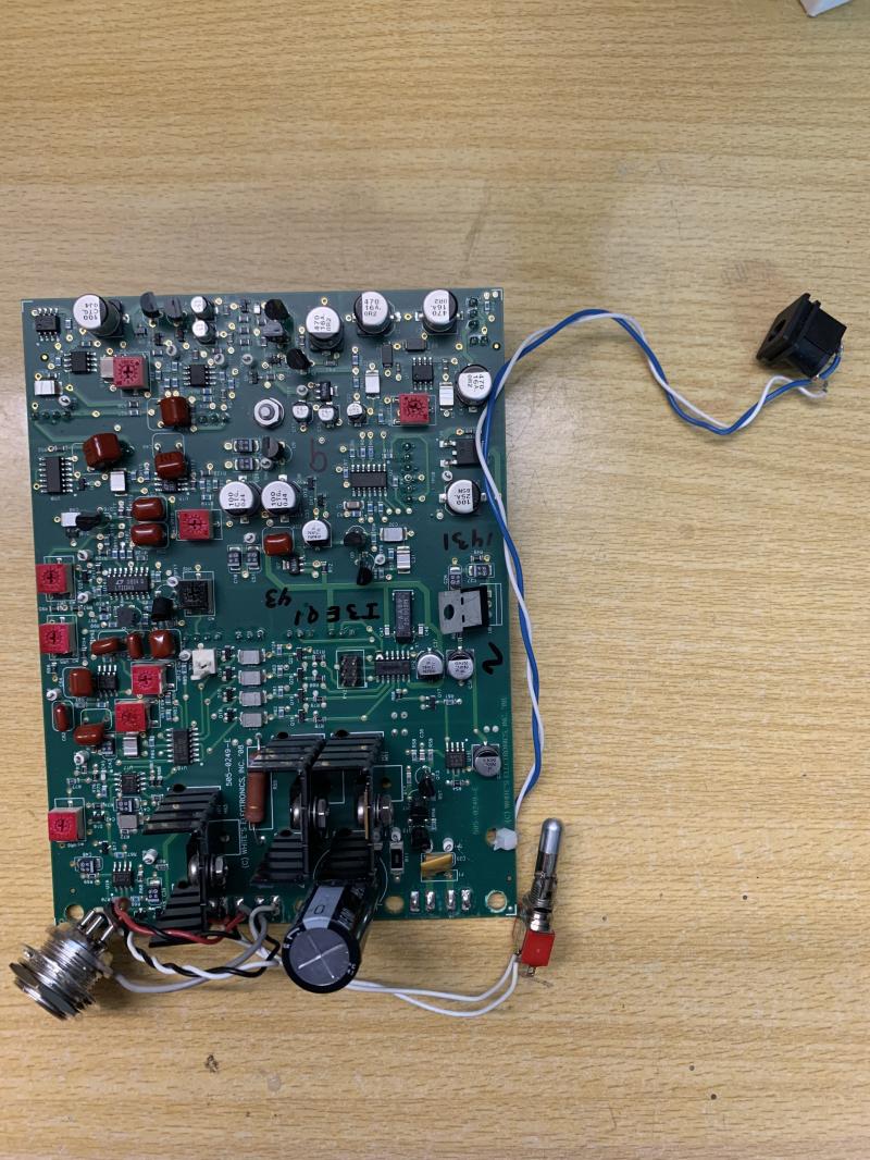
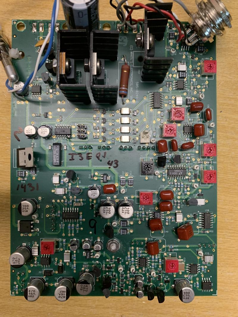
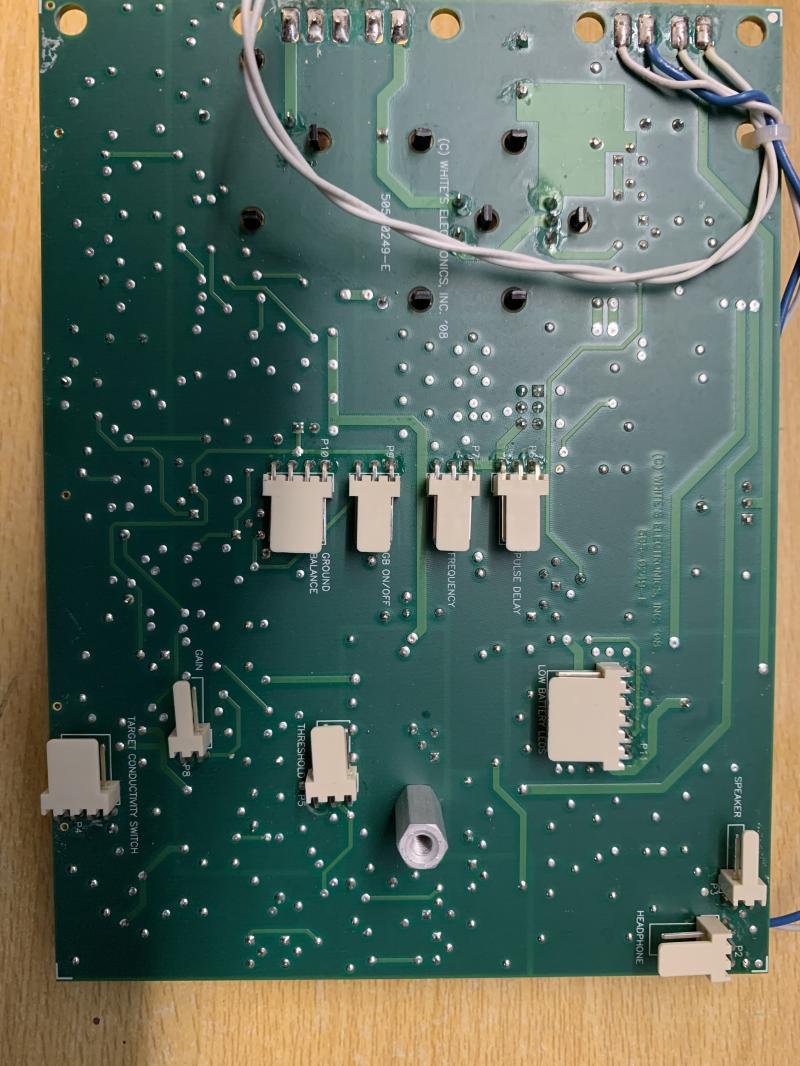
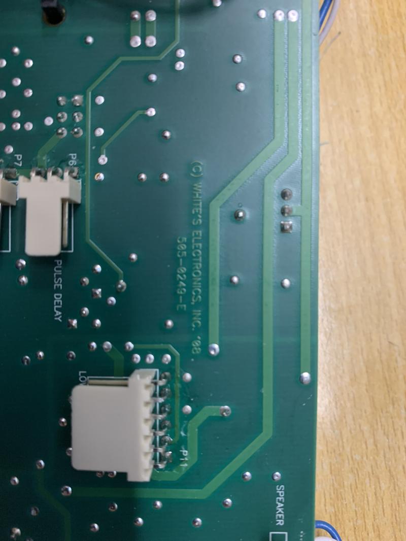
Not JST, I think KF2510 Connector.
The conductivity switch must be connected to an outlet with 4 pins connector (board).
Does it go on a 3-pin or 6-pin OFF-ON-OFF switch?
Because in the case of a 3-pin, do we connect the two pins in the middle of the connector to the same middle contact of the switch?
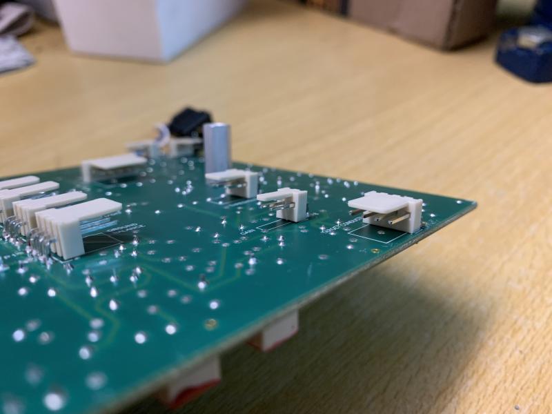
Leave a comment:
-
Most of this is repeated from Steve's forum:
Pulse delay & Frequency are 10k, although 100k will also work.
Gain is 50k.
Ground balance is 100k.
Threshold is 100k.
All pots are mono.
As I recall the PCB is marked where everything plugs in. The pin connections are all linear, that is, outside-middle-outside on the pot (or switch) is the same on the connector. This means you will have to figure out which outside connection goes where but that's pretty easy once you fire up the circuit. If the pot operation is backwards, swap the outside pins. Sorry, I don't have a diagram or a pic.
However, JST connectors (1.25mm) were used on the TDI-SL board, I don't recall they were ever used on the TDI board. They should be 0.1" pin connectors. Can you post a photo?Leave a comment:
-
Whites TDI : Pots & switchs values/position
Hi,
Having just a TDI board and a coil, I would like to reassemble the detector complety.
So I wanted to know what are the values of the different potentiometers, if the switches are just on/off?
And also photos to know where each conductor goes in the JST connector on the board and the potentiometers/switches?
Thanks.
David
Leave a comment: