Announcement

Collapse
No announcement yet.

New Bipolar Boost TX and Front End

Collapse
X
 
  • Filter
  • Time
  • Show
Clear All
new posts

  • KingJL
    replied
    Originally posted by green View Post
    Any updates?
    Updates... no (not yet)... changes, yes (many). There is a new finalized PCB layout... boards have been fab'd and are (slowly... we are in no hurry) being populated for testing. New boards are: single board layout (power supply still on separate board); using ADuM4120 for MOSFET gate drive vs previous pulse transformer method; moved to use external (from FPGA) AD4020 20 bit ADC for RX signal processing; changed a few parts to less costly variants (some requiring different footprints); internal FPGA XADC used for TX voltage monitoring/control; developed a single bit DAC FPGA module for control of TX voltage; configurable coil resistance parameter used to control TX voltage; automatic adjustment of TX boost duration to flatten TX current profile; successfully interfaced to Nextion display@115200 bps via software configurable serial port; implemented serial send queue for serial FPGA/Nextion message traffic that is interrupt based... send and forget; developed a method that attempts to maintain a constant false alarm rate (fast attack/slow decay... targeted CFAR of 0.5%) using sample 3 to set threshold; limiting total RX time to about 80 usec after TX-OFF; disable step-up voltage regulator pump during TX & RX period; successfully implemented storage of TX & RX parameters in Nextion EEPROM.

    Updates will occur when actual board testing begins and there are actual meaningful results to publish/report.

    Leave a comment:


  • green
    replied
    Any updates?

    Leave a comment:


  • eclipse
    replied
    Thanks for the efforts, keep us posted with the progress.

    Leave a comment:


  • KingJL
    replied
    Originally posted by eclipse View Post
    In the datasheet is says

    Logic Input Voltage
    High 0.7 x VDD1
    Low 0.3 x VDD1
    @eclipse, I was just reporting what I have observed. In fact, the single board ADuM Bipolar design will be using 3.3V for Vdd1 from the same regulator that supplies 3.3V to the LTC2378-20. There are some significant design changes in the power management of the single board that will be reflected in the next release of the development effort. Mdtoday is currently finalizing the ADuM power supply. When the PS design/layout is finalized the ADuM single board will be synced with the PS requirements.

    Leave a comment:


  • eclipse
    replied
    In the datasheet is says

    Logic Input Voltage
    High 0.7 x VDD1
    Low 0.3 x VDD1

    Leave a comment:


  • KingJL
    replied
    Originally posted by eclipse View Post
    About the Adum version. I think Vdd1 supply for the ADuM4120 should be 3.3V if we want to drive it with 3.3V signal.
    It still works with Vdd1 of 5V and logic levels of 3.3. Testing has shown the low/high threshold to be 1.5-2V (worst case specified at 2.5V) with Vdd1 at 5V.

    Leave a comment:


  • eclipse
    replied
    About the Adum version. I think Vdd1 supply for the ADuM4120 should be 3.3V if we want to drive it with 3.3V signal.

    Leave a comment:


  • waltr
    replied
    I started a PIC32 programing thread here for continued discussion.
    This is a special section dedicated to coding techniques, tips, tricks, methodology, programming various modules, MCUs, digital filters, etc. Basically, anything code-related.


    Please post there any PIC32 question, etc

    Leave a comment:


  • eclipse
    replied
    You got one from me as a free gift or if you prefer the Whiskey deal! Send me a PM with your choice.

    Leave a comment:


  • waltr
    replied
    Originally posted by ivconic View Post
    Cool stuff!
    Waltr what dev kit you are using?
    I've been searching the net to see what's available.
    I have the Microchip Curiosity PIC32MZ EF 2.0 dev board.


    It has on board a PKoB4 programmer/debugger. Down side is the Odd set of connectors then they total scr***ed up two of the Arduino connectors (reversed the routing).

    Originally posted by eclipse View Post
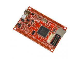
    If you're looking for PIC32MZ dev board, check this out (it uses PIC32MZ2048EFM144, same as waltr dev board)

    Development board with PIC32MZ2048EFМ144 running at 200Mhz and with 2MB of Flash and 512KB SRAM


    I've made my own board suitable for a basic development.
    Yes, the Olimex dev bd has the same processor but needs a separate programmer/debugger like the PICKit3 or 4.
    For what it is it is a good price. Tempting to get one.

    Leave a comment:


  • 6666
    replied
    Originally posted by eclipse View Post
    If you're looking for PIC32MZ dev board, check this out (it uses PIC32MZ2048EFM144, same as waltr dev board)

    Development board with PIC32MZ2048EFМ144 running at 200Mhz and with 2MB of Flash and 512KB SRAM


    I've made my own board suitable for a basic development.

    This caught my eye on that link, thanks,
    PIC32-PINGUINO-OTG

    Leave a comment:


  • ivconic
    replied
    Originally posted by eclipse View Post
    If you're looking for PIC32MZ dev board, check this out (it uses PIC32MZ2048EFM144, same as waltr dev board)

    Development board with PIC32MZ2048EFМ144 running at 200Mhz and with 2MB of Flash and 512KB SRAM


    I've made my own board suitable for a basic development.
    Bingo!
    I just wanted to ask about Olimex kits!

    Leave a comment:


  • eclipse
    replied
    If you're looking for PIC32MZ dev board, check this out (it uses PIC32MZ2048EFM144, same as waltr dev board)

    Development board with PIC32MZ2048EFМ144 running at 200Mhz and with 2MB of Flash and 512KB SRAM


    I've made my own board suitable for a basic development.

    Leave a comment:


  • ivconic
    replied
    Cool stuff!
    Waltr what dev kit you are using?
    I've been searching the net to see what's available.

    Leave a comment:


  • waltr
    replied
    Originally posted by eclipse View Post
    Oh man thanks would never have figure it out. I was really stuck. I owe you a nice bottle of whiskey!
    No problem. That is why we have this forum.
    These PIC processors are very peripheral rich and takes a good bit of study to figure them out.

    I have a PIC32MX running a PI detector using the OC module to run TX pulse.
    As in the code I posted, the OC Interrupt then starts a timer (TMR3) that triggers ADC conversions. The ADC Interrupt Flag then triggers a data transfer from ADC to memory using DMA. This puts TX pule to ADC data in memory all in Hardware.
    Then in the Main loop, code waits for DMA block transfer to finish and moves this data to working buffer to process.
    This is running ADC conversion at 2usec and collect 128 samples after each TX pulse.

    The PIX32MZ EF has a much more complex ADC and I having been struggling to get the ADC -> memory by DMA working correctly.

    Leave a comment:

Working...
X