
 Tweet
Tweet
Originally posted by green
View Post
-
Thanks for posting the sim. From what Zed stated his low R and C values generate more heat than my higher value RC values. At some point I'll try a comparison of the two models in my circuit. The zeds version is faster acting and probably has less affect on the flyback period? -
Simulation for my 30inch DD coil snubbed at 400V. 100nF capacitor looks alright.Comment
-
Altra I forgot to mention,I also have a 100k resistor in parallel with the snubber cap.this drains the cap a little for the next cycle.Comment
-
Hi green
Thanks for all your great efforts to visual presentation (simulations) of circuit events.
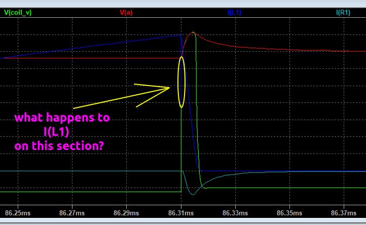
I do not understand part of your last simulation graph.
Can you explain a little bit, what happens to I(L1) on this graph section? Thanks.
Comment
-
Green im a bit puzzled by the zener models that LTspice has supplied and that you are using,im using a different diode and avalanching it at 200v and i get a lot more current going through it,see my simComment
-
I'm guessing you are asking about the glitch caused when coil Cpar is being charged.Originally posted by WM6 View PostComment
-
-
Hadn't tried doing math with sim traces. An attempt to see where the power is being dissipated. Anyone see if I'm doing something wrong or missing something?Comment
-
Can get the average watts of the trace with spice. For https://www.geotech1.com/forums/atta...1&d=1593096171
Zener watts=1.95W
R2(R damping)=.578W
R1=.085W
sum=2.613W
Coil watts(calculated)=2.64W, close to the sum [Coil power(watts)at Tx off=peak current*peak current*coil inductance*Tx pps/2]Comment
-
Calculated coil power for your sim. =3.24W. Got 2.63W for D3, changing C1 didn't have much effect on D3 power dissipation. Just playing, learning.Originally posted by ZED View PostComment
-
For practice I did Zed's sim again
Power for Zed's sim. https://www.geotech1.com/forums/atta...7&d=1593069271
Coil power=3.24W
D3=2.28W
R1=.597W
R2=.4W
R3=.019W
D3 not the same as I got rely #85. Maybe I do need more practice.Comment
-
Sweet ! & thanks green.
Im using a 1/4 what resistor for R2 (1206),think i might need to beef it up a bit if theres 0.4 watts of power going through it.
R1 is ok its two 1 watt 1k thin film melfs in parrellel
D3 is a 1watt diode...hmmm.
So would C1 be roughly 4.2 watts ?Comment
-
I'm guessing C1 would be close to zero watts. Maybe a little do to ESR?Originally posted by ZED View PostComment
-
Don't forget voltage ratings, that's why I use higher wattage parts even if overkill. Higher wattage resistors tend to also have higher voltage rating. Less heat less noise.Originally posted by ZED View PostComment
-
Ummm what about when the coil current gets dumped into the capacitor at the end of the TX period ? My sim shows 3 amps.Originally posted by green View PostComment
Comment