Announcement

Collapse
No announcement yet.

Delta Pulse - Take 2

Collapse
X
 
  • Filter
  • Time
  • Show
Clear All
new posts

  • Faroukbns
    replied
    Hi to all
    I'm New in this forum
    I would like to know the difference between the sniffer xr71 and delta pulse2 and which is the best for Roman treasures
    Thanks

    Leave a comment:


  • kt315
    replied
    Starina Schoolts gives recommendations https://www.youtube.com/watch?v=dpjQe-CxP-k

    Leave a comment:


  • kt315
    replied
    thank you for warm recipe.
    'Take Two' (c)

    Leave a comment:


  • Bayu
    replied
    hello all, these few days I tried to experiment with DP like the following photo,
    I changed my R5 to 470r
    I changed my R6 220r
    frequency 300hz
    induction coil 300-320 uH
    then I changed the resistor near 14538 as in the photo * with a 503 trimpot to adjust the timing on T4 and T5
    T4 which on the 40us scheme I changed to 22us
    T5 100us,
    good detection results with plato pliers which was 40cm points, now 50cm points.
    the gold ring that used to have to be attached to the coil, now can be 18cm points,
    that's my experience with DPClick image for larger version

Name:	Screenshot_2022_0920_224913.png
Views:	1
Size:	743.7 KB
ID:	363424Click image for larger version

Name:	IMG_20220910_184214.jpg
Views:	1
Size:	1.03 MB
ID:	363425Click image for larger version

Name:	Screenshot_2022_0920_224848.png
Views:	1
Size:	867.1 KB
ID:	363426

    Leave a comment:


  • kt315
    replied
    glad to see you in game.
    second board is for any impulse power supply (PS) with two and more output voltages. you have to load all outputs by load, by resistors.
    another way this is useful for trash tech if you take/find/use PS from trash electronics - tv sets, videorecorders, LAN modems etc.
    right loading of PS gives you right stabile work of PS. 'loader board'. all types of resistors are fitting, 1..2..5..10Watt.
    sometimes a PS does not wish to turn on... that is.
    good and mandatory for laboratory PS, 'always on table and in use'.

    Leave a comment:


  • Infamy
    replied
    Originally posted by kt315 View Post
    i am not all time at home. i see all your requests do not worry pls.
    Thanks for the board, arrived yeasterday. Just wondering what the second board is, R1-R4.

    Leave a comment:


  • kt315
    replied
    i am not all time at home. i see all your requests do not worry pls.

    Leave a comment:


  • wtrk
    replied
    Can you please give me permission

    Leave a comment:


  • kt315
    replied
    reloaded.
    just DP files https://drive.google.com/file/d/1EIo...ew?usp=sharing
    whole archive https://drive.google.com/file/d/1zyQ...ew?usp=sharing

    Leave a comment:


  • Infamy
    replied
    Hi can some direct me to the gerber file for the last Rev of Delta Pulse.
    If there is an up to date parts last that would be helpful.
    Thanks.

    Leave a comment:


  • Ssqqar12
    replied
    Please, how can I add a tone key to this version?Click image for larger version

Name:	Screenshot_٢٠٢٢٠٦٢٥-١٥٥٧.png
Views:	1
Size:	365.4 KB
ID:	363075Click image for larger version

Name:	Screenshot_٢٠٢٢٠٦٢٥-١٥٥٧.png
Views:	1
Size:	365.4 KB
ID:	363075

    Leave a comment:


  • Ssqqar12
    replied
    Is it possible to find an editable file for this device ?

    Leave a comment:


  • Stevedbk
    replied
    Originally posted by Sally View Post
    Yes I did check all the components before putting on the board. I used resistor 1/4 watts 1% and measured it before soldering.
    For capacitors I did check the value up to the range of my LCR. Smaller values like pico farads cannot check because it has limited range.
    To measure small values, first measure a larger value that your meter can read. Then place your unknown value is parallel and read again. The difference is your unknown value.
    Steve

    Leave a comment:


  • kt315
    replied
    for a member.

    take analog arrow chinese tester ('simplest'). it has 0.5mA scale. yes, that is DC but you measure DC =)
    ie 0.1 division of it is 100uA. connect to R37 and write what you see.
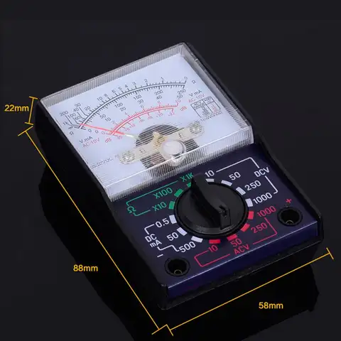
    Attached Files

    Leave a comment:


  • Sally
    replied
    Originally posted by surfdetector View Post
    Pulse Width OUT = RC (PW in seconds, R in Ohms, C in Farads)
    Have you checked your component values?
    Yes I did check all the components before putting on the board. I used resistor 1/4 watts 1% and measured it before soldering.
    For capacitors I did check the value up to the range of my LCR. Smaller values like pico farads cannot check because it has limited range.

    Leave a comment:

Working...
X